Pneumatic Manoeuvring Diagram, CPP
509 12 04-5.1.0
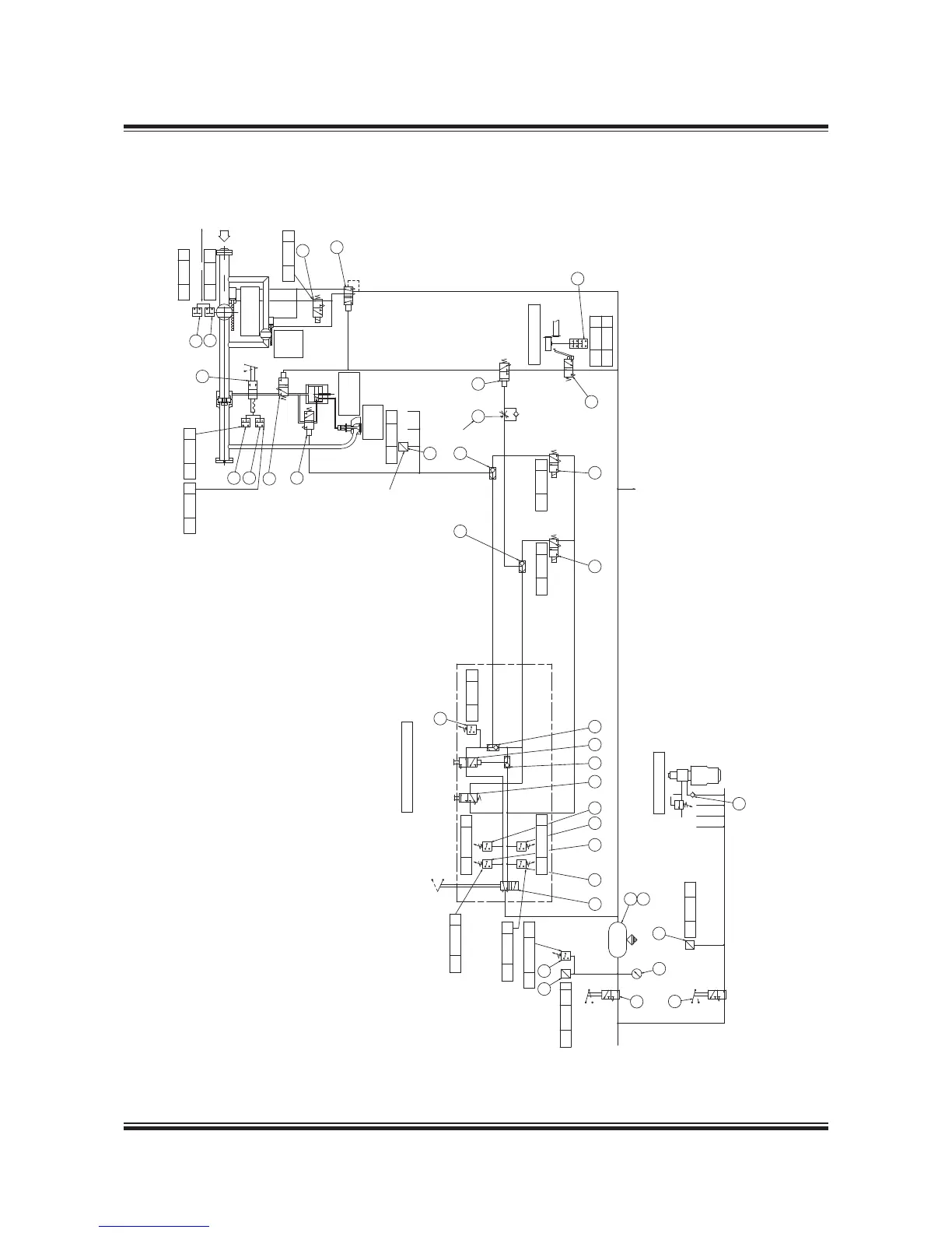
Fig. 16.01.04b: Pneumatic Manoeuvring Diagram, Controllabe Pitch Propeller (CPP)
Service / Blocked
4
2
14
2
1
3
12
1
3
2
1
ø16x2
Turning gear
2
1
4
14
2
ø16x2
ø16x2
118
121
120
116
32
119
117
5
B
A
P
S
R
115
27
33
90
1
20
6
1
4
12
3
A
R1
P1
A
R1
P1
5
6
162
84
163 103
100
P1
A
R1
R1
P1
A
101 102
B
A, B refer to list of ‘Counterflanges’
A
B
26
A
21
Output for
Oil Mist Detector
Subfunction 217410
48
85
91
137
114
3
5
PS 1106 C
ZV 1136 C
ZV 1137 C
ZV 1109 C
ZS 1112 C
ZS 1111 C
ø16x2
ø16x2
A
R2P2
Slowturning
28
ZV 1114 C
PS 11182 C
PS 11181 C
PS 11301 C
83
107
PS 85032 AH
PT 8503 AL I
2 4
138
PT 8505 AL
ZV 1110 C
PT 1101 C
160
One pressure transmitter
per CCUunit
108
20 L
Pipe dimevnsion ø10x1.5
except where otherwise stated
The drawing shows the system in the following conditions:
Manual control
Stop position,
Pneumatic pressure on,
El. power on,
Main starting valve locking device in service position.
Safety relief valve
set point: 23 bar
Exhaust valve
Control Air
Supply
StopStart
Stop
Stop
Start
Start
Engine side console
Remote control
Manual control
Set point: 1 sec.
Starting
valve
Starting air
distributor
Main starting
valve
Slow
turning
valve
PS 11302 C
ZS 1116 C
ZS 1117 C
 Loading...


