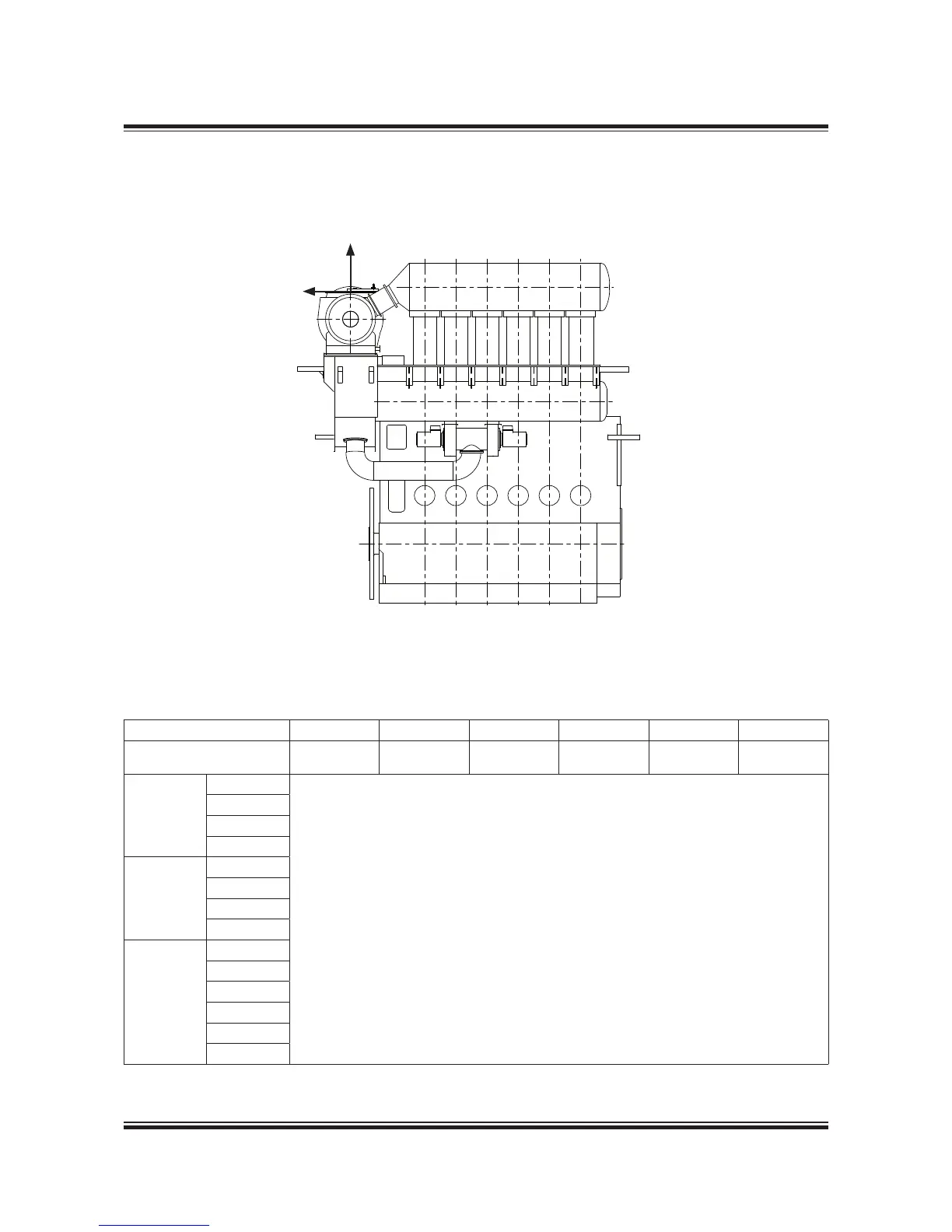
Fig. 15.06.01b: Vectors of thermal expansion at the turbocharger exhaust gas outlet flange, TC on aft end
078 87 11-1.0.0a
Table 15.06.02b: Max. expected movements of the exhaust gas flange resulting from thermal expansion, TC on aft end
No. of cylinders 5-9 5 6 7 8 9
Turbocharger DA DC DC DC DC DC
Make Type mm mm mm mm mm mm
MAN
TCA44
Available on request
TCA55
TCA66
TCA77
ABB
A265
A170 / A270
A175 / A275
A180
MHI
MET42
MET48
MET53
MET60
MET66
MET71
DA: Max. movement of the turbocharger flange in the vertical direction
DC: Max. movement of the turbocharger flange in the longitudinal direction
One turbocharger located on aft end
 Loading...


