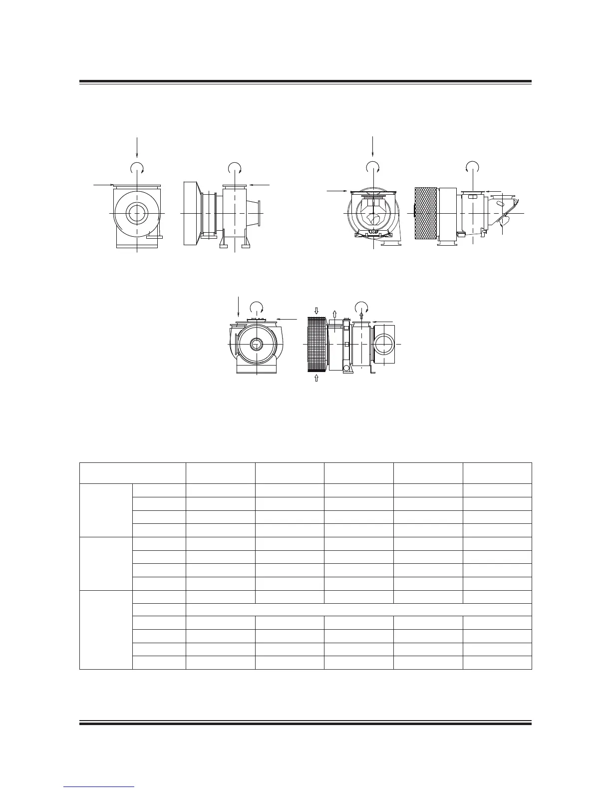
Table 15.06.04 indicates the maximum permissi-
ble forces (F1, F2 and F3) and moments (M1 and
Table 15.06.04: The max. permissible forces and moments on the turbocharger’s gas outlet flanges
Turbocharger M1 M3 F1 F2 F3
Make Type Nm Nm N N N
MAN
TCA44 3,200 6,400 8,500 8,500 4,200
TCA55 3,400 6,900 9,100 9,100 4,500
TCA66 3,700 7,500 9,900 9,900 4,900
TCA77 4,100 8,200 10,900 10,900 5,400
ABB
A265 1,200 1,200 2,800 1,800 1,800
A170 / A270 1,900 1,900 3,600 2,400 2,400
A175 / A275 3,300 3,300 5,400 3,500 3,500
A180 4,600 4,600 6,800 4,400 4,400
MHI
MET42 3,400 1,700 5,800 2,000 1,800
MET48 Available on request
MET53 4,900 2,500 7,300 2,600 2,300
MET60 6,000 3,000 8,300 2,900 3,000
MET66 6,800 3,400 9,300 3,200 3,000
MET71 7,000 3,500 9,600 3,300 3,100
078 38 48-6.2.2
M1 M3
F3
F3F2
F1
MAN
M1
F2
F1
Mitsubishi
M3
ABB A-L
M1
F1
F2
M3
F3
Fig. 15.06.03: Forces and moments on the turbochargers’ exhaust gas outlet flange
M3), on the exhaust gas outlet flange of the turbo-
charger(s). Reference is made to Fig. 15.06.03.
 Loading...


