Expansion joint
option: 4 60 610
Transition piece
option: 4 60 601
D4
D0
D4
D4
Centre line turbocharger
Diameter of Exhaust Gas Pipes
178 09 395.2r
Gas velocity Exhaust gas pipe diameters
35 m/s 40 m/s 45 m/s 50 m/s D0 D4
Gas mass flow 1 T/C 2 T/C 3 T/C
kg/s kg/s kg/s kg/s [DN] [DN] [DN] [DN]
15.0 17.2 19.3 21.5 900 650 500 900
16.7 19.1 21.5 23.9 950 650 550 950
18.6 21.2 23.9 26.5 1,000 700 600 1,000
20.5 23.4 26.3 29.2 1,050 750 600 1,050
22.4 25.7 28.9 32.1 1,100 800 650 1,100
24.5 28.0 31.5 35.1 1,150 800 650 1,150
26.7 30.5 34.3 38.2 1,200 850 700 1,200
31.4 35.8 40.3 44.8 1,300 900 750 1,300
36.4 41.6 46.8 51.9 1,400 1,000 800 1,400
41.7 47.7 53.7 59.6 1,500 1,050 850 1,500
47.5 54.3 61.1 67.8 1,600 1,150 900 1,600
D0
Fixed point
Centre line turbocharger
D0
Expansion joint
option: 4 60 610
Transition piece
option: 4 60 601
178 31 598.1r
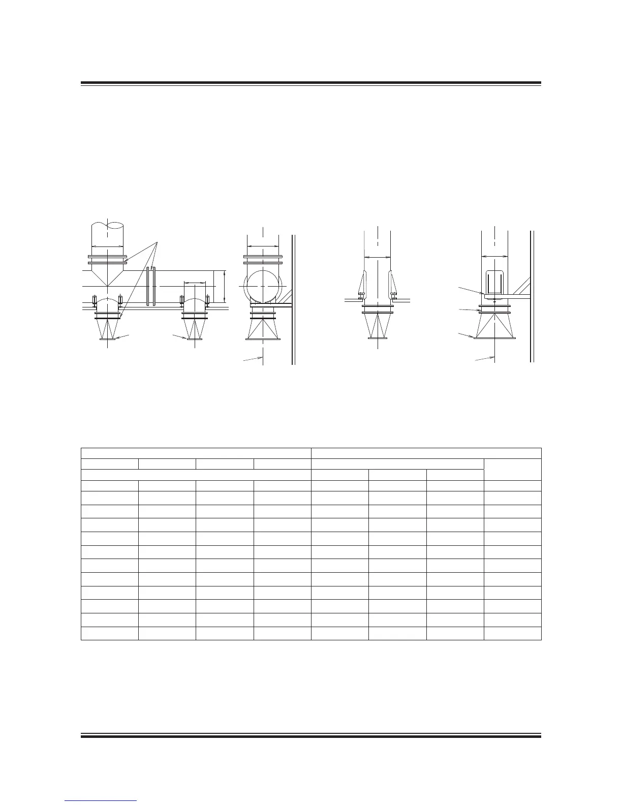
Fig. 15.07.01a: Exhaust pipe system, with turbocharger
located on exhaust side of engine, option: 4 59 123
Fig. 15.07.01b: Exhaust pipe system, with single turbo-
charger located on aft end of engine, option: 4 59 121
Table 15.07.02: Exhaust gas pipe diameters and exhaust gas mass flow at various velocities
The exhaust gas pipe diameters listed in Table
15.07.02 are based on the exhaust gas flow ca-
pacity according to ISO ambient conditions and
an exhaust gas temperature of 250 ºC.
The exhaust gas velocities and mass flow listed
apply to collector pipe D4. The table also lists the
diameters of the corresponding exhaust gas pipes
D0 for various numbers of turbochargers installed.
 Loading...


