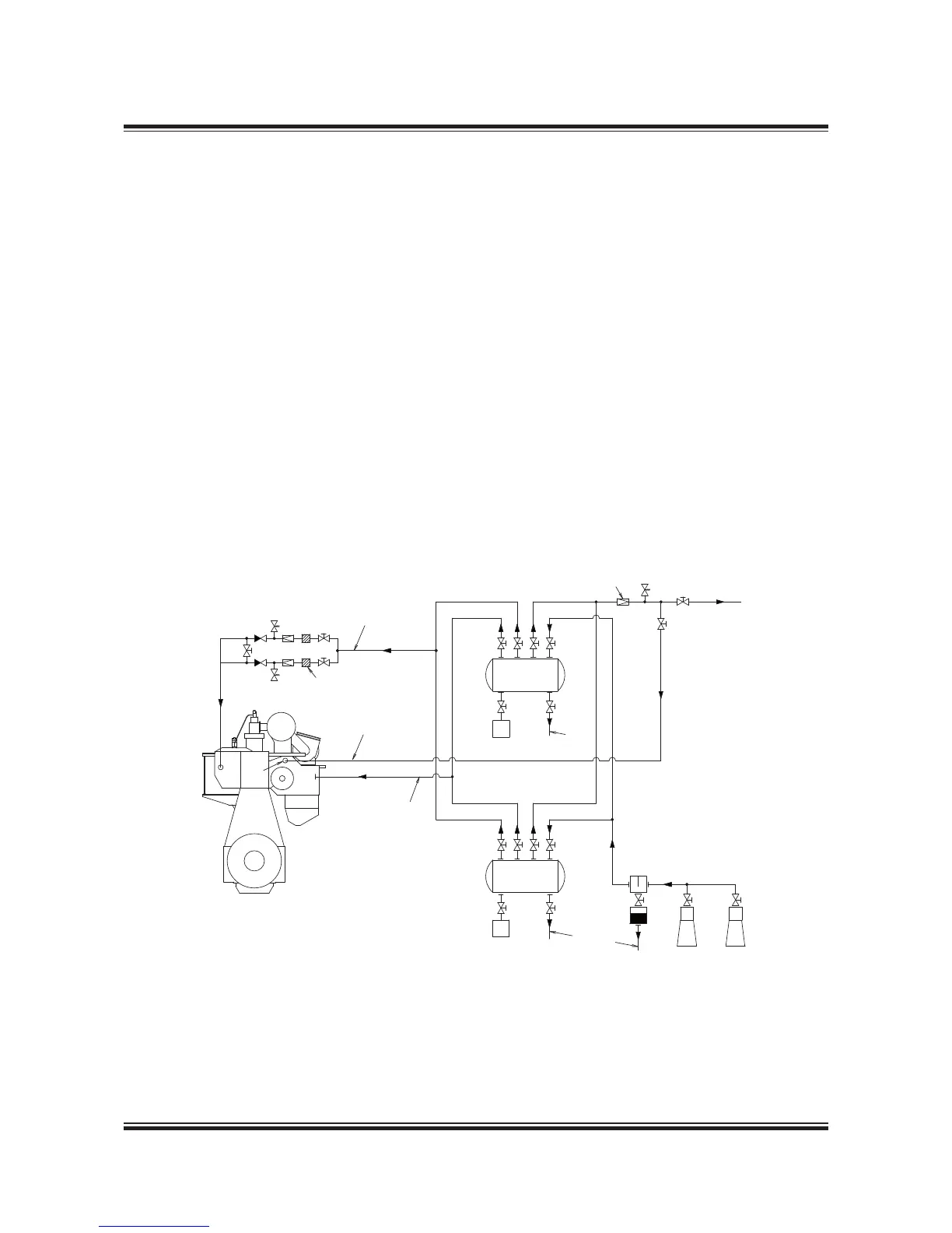
Fig. 13.01.01: Starting and control air systems
The starting air of 30 bar is supplied by the start-
ing air compressors to the starting air receivers
and from these to the main engine inlet ‘A’.
Through a reduction station, filtered compressed
air at 7 bar is supplied to the control air for ex-
haust valve air springs, through engine inlet ‘B’
Through a reduction valve, compressed air is sup-
plied at 10 bar to ‘AP’ for turbocharger cleaning
(soft blast), and a minor volume used for the fuel
valve testing unit.
Please note that the air consumption for control
air, safety air, turbocharger cleaning, sealing air
for exhaust valve and for fuel valve testing unit are
momentary requirements of the consumers.
The components of the starting and control air
systems are further desribed in Section 13.02.
For information about a common starting air sys-
tem for main engines and MAN Diesel auxiliary
engines, please refer to our publication:
Uni-concept Auxiliary Systems for Two-Stroke Main
Engines and Four-Stroke Auxiliary Engines
The publication is available at www.marine.man.eu
→ ’Two-Stroke’ → ’Technical Papers’.
078 83 76-7.3.0
Oil & water
separator
To bilge
Reduction station
Pipe, DN25 mm
Pipe a, DN *)
Starting air
receiver 30 bar
Starting air
receiver 30 bar
Filter,
40 µm
To
bilge
Main
engine
Air compressors
To fuel valve
testing unit
B AP
A
Reduction valve
PI
PI
Pipe, DN25 mm
The letters refer to list of ‘Counterflanges’
*) Pipe a nominal dimension: DN100 mm
Starting and Control Air Systems
 Loading...


