MAN B&W 7.05
Page 3 of 3
MAN Diesel
MAN B&W MC/MC-C, ME/ME-C/ME-B/-GI engines,
MC/ME Engine Selection Guides
198 47 35-0.3
Fuel oil filter
The filter can be of the manually cleaned duplex
type or an automatic filter with a manually cleaned
bypass filter.
If a double filter (duplex) is installed, it should
have sufficient capacity to allow the specified full
amount of oil to flow through each side of the filter
at a given working temperature with a max. 0.3
bar pressure drop across the filter (clean filter).
If a filter with backflushing arrangement is
installed, the following should be noted. The re-
quired oil flow specified in the ‘List of capacities’,
i.e. the delivery rate of the fuel oil supply pump and
the fuel oil circulating pump, should be increased
by the amount of oil used for the backflushing, so
that the fuel oil pressure at the inlet to the main en-
gine can be maintained during cleaning.
In those cases where an automatically cleaned
filter is installed, it should be noted that in order
to activate the cleaning process, certain makers of
filters require a greater oil pressure at the inlet to
the filter than the pump pressure specified. There-
fore, the pump capacity should be adequate for
this purpose, too.
The fuel oil filter should be based on heavy fuel oil
of: 130 cSt at 80 °C = 700 cSt at 50 °C = 7000 sec
Redwood I/100 °F.
Fuel oil flow ......................... see ‘List of capacities’
Working pressure .......................................... 10 bar
Test pressure ...................... according to class rule
Absolute fineness .......................................... 50 µm
Working temperature .................. maximum 150 °C
Oil viscosity at working temperature ............15 cSt
Pressure drop at clean filter ........maximum 0.3 bar
Filter to be cleaned at a pressure
drop of ........................................maximum 0.5 bar
Note:
Absolute fineness corresponds to a nominal fine-
ness of approximately 35 µm at a retaining rate of
90%.
The filter housing shall be fitted with a steam jack-
et for heat tracing.
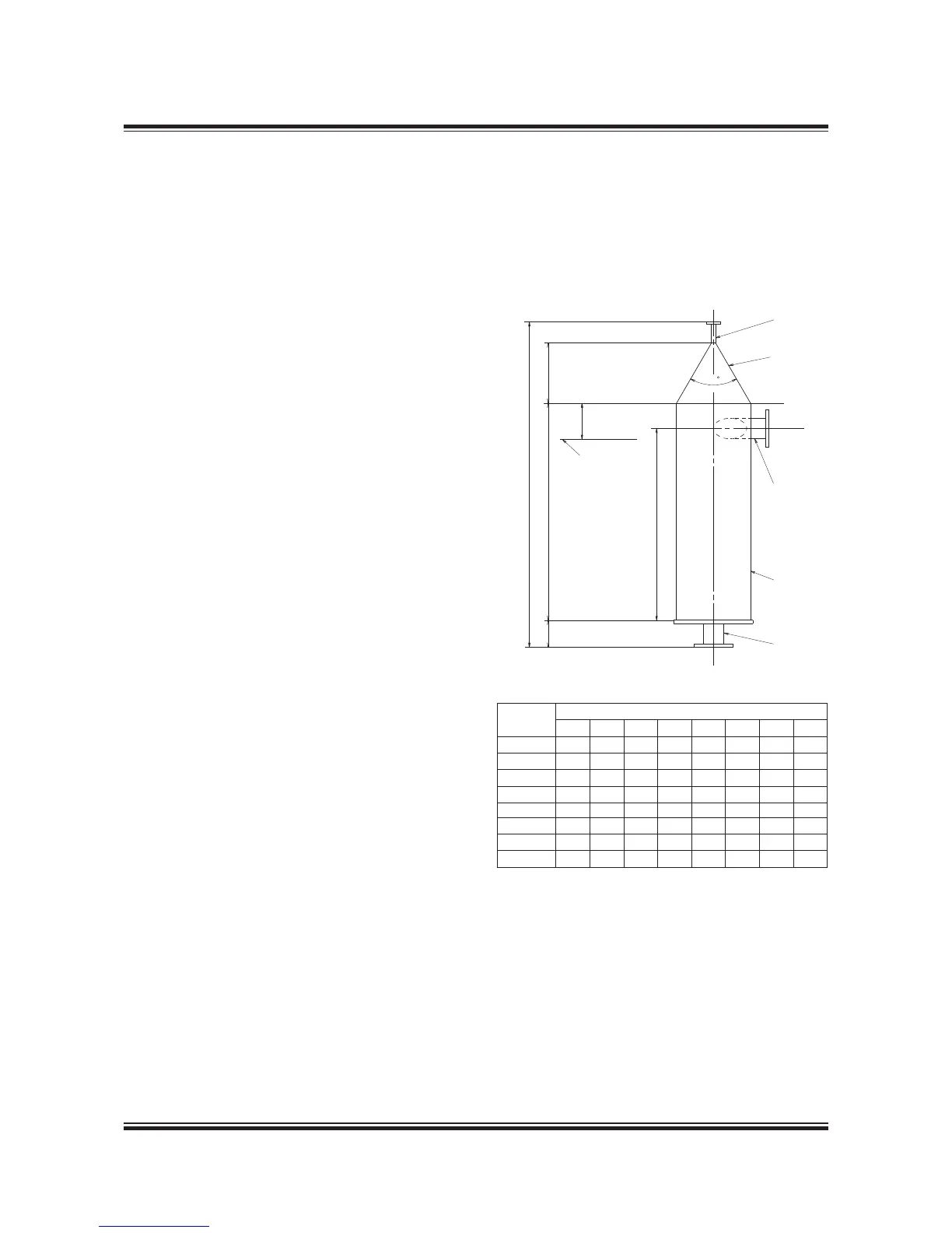
Fuel oil venting box
The design of the Fuel oil venting box is shown in
Fig. 7.05.02. The size is chosen according to the
maximum flow of the fuel oil circulation pump,
which is listed in section 6.03.
178 38 393.3
Flushing of the fuel oil system
Before starting the engine for the first time, the
system on board has to be flushed in accord-
ance with MAN Diesel & Turbos recommendations
‘Flushing of Fuel Oil System’ which is available on
request.
Flow m
3
/h
Q (max.)*
Dimensions in mm
D1 D2 D3 H1 H2 H3 H4 H5
1.3 150 32 15 100 600 171.3 1,000 550
2.1 150 40 15 100 600 171.3 1,000 550
5.0 200 65 15 100 600 171.3 1,000 550
8.4 400 80 15 150 1,200 333.5 1,800 1,100
11.5 400 90 15 150 1,200 333.5 1,800 1,100
19.5 400 125 15 150 1,200 333.5 1,800 1,100
29.4 500 150 15 150 1,500 402.4 2,150 1,350
43.0 500 200 15 150 1,500 402.4 2,150 1,350
* The maximum flow of the fuel oil circulation pump
Fig. 07.05.02: Fuel oil venting box
 Loading...


