PTO/RCF
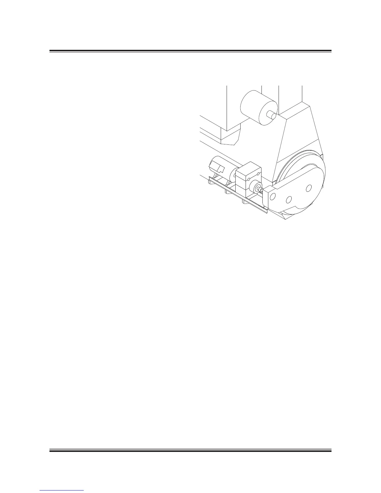
Side mounted generator, BW III/RCF
(Fig. 4.01.01, Alternative 3)
The PTO/RCF generator systems have been de-
veloped in close cooperation with the German
gear manufacturer RENK. A complete package
solution is offered, comprising a flexible coupling,
a stepup gear, an epicyclic, variableratio gear
with builtin clutch, hydraulic pump and motor,
and a standard generator, see Fig. 4.01.04.
For marine engines with controllable pitch propel-
lers running at constant engine speed, the hydrau-
lic system can normally be omitted. For constant
speed engines a PTO/GCR design is normally
used.
Fig. 4.01.04 shows the principles of the PTO/
RCF arrangement. As can be seen, a stepup
gear box (called crankshaft gear) with three gear
wheels is bolted directly to front- and part side
engine crankcase structure. The bearings of the
three gear wheels are mounted in the gear box so
that the weight of the wheels is not carried by the
crankshaft. Between the crankcase and the gear
drive, space is available for tuning wheel, counter-
weights, axial vibration damper, etc.
The first gear wheel is connected to the crank-
shaft via a special flexible coupling, made in one
piece with a tooth coupling driving the crankshaft
gear, thus isolating the gear drive against torsional
and axial vibrations.
By means of a simple arrangement, the shaft in
the crankshaft gear carrying the first gear wheel
and the female part of the toothed coupling can
be moved forward, thus disconnecting the two
parts of the toothed coupling.
The power from the crankshaft gear is trans-
ferred, via a multidisc clutch, to an epicyclic
variableratio gear and the generator. These are
mounted on a common PTO bedplate, bolted to
brackets integrated with the engine crankcase
structure.
178 06 49-0.0
The BW III/RCF unit is an epicyclic gear with a
hydrostatic superposition drive. The hydrostatic
input drives the annulus of the epicyclic gear in ei-
ther direction of rotation, hence continuously vary-
ing the gearing ratio to keep the generator speed
constant throughout an engine speed variation of
30%. In the standard layout, this is between 100%
and 70% of the engine speed at specified MCR,
but it can be placed in a lower range if required.
The input power to the gear is divided into two
paths – one mechanical and the other hydro-
static – and the epicyclic differential combines the
power of the two paths and transmits the com-
bined power to the output shaft, connected to the
generator. The gear is equipped with a hydrostatic
motor driven by a pump, and controlled by an
electronic control unit. This keeps the generator
speed constant during single running as well as
when running in parallel with other generators.
Fig. 4.01.03: Side mounted BW III/RCF
 Loading...


