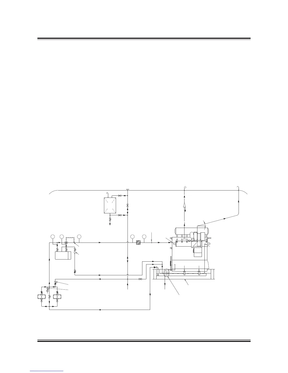
Lubricating and Cooling Oil System
Thermostatic valve
TI TI TI
Lube. oil
cooler
For initial fillling of pumps
Pos. 006: 25 mm valve
for cleaning process
Lube oil pumps
Engine
oil
PI PI
Fullflow filter
RU
AR
E
AB
Min. 15°
Lube oil bottom tank
with cofferdam
To purifier
From purifier
Deck
To drain tank
Pos. 005: throttle valve
Deaeration
Feeler, 45 °C
*
S S
Servo oil backflushing
see Section 8.08
RW
The letters refer to list of ‘Counterflanges’
* Venting for MAN Diesel or Mitsubishi turbochargers only
198 99 844.5
The lubricating oil is pumped from a bottom tank
by means of the main lubricating oil pump to the
lubricating oil cooler, a thermostatic valve and,
through a fullflow filter, to the engine inlet RU, Fig.
8.01.01.
RU lubricates main bearings, thrust bearing, axial
vibration damper, piston cooling, crosshead bear-
ings, crankpin bearings. It also supplies oil to the
Hydraulic Power Supply unit and to the torsional
vibration damper.
From the engine, the oil collects in the oil pan,
from where it is drained off to the bottom tank,
see Fig. 8.06.01a and b ‘Lubricating oil tank, with
cofferdam’. By class demand, a cofferdam must
be placed underneath the lubricating oil tank.
The engine crankcase is vented through ‘AR’ by a
pipe which extends directly to the deck. This pipe
has a drain arrangement so that oil condensed in
the pipe can be led to a drain tank, see details in
Fig. 8.07.01.
Drains from the engine bedplate ‘AE’ are fitted on
both sides, see Fig. 8.07.02 ‘Bedplate drain pipes’.
For external pipe connections, we prescribe a
maximum oil velocity of 1.8 m/s.
Lubrication of turbochargers
Turbochargers with slide bearings are normally
lubricated from the main engine system. AB is
outlet from the turbocharger, see Figs. 8.03.01 to
8.03.04.
Figs. 8.03.01 to 8.03.04 show the lube oil pipe ar-
rangements for different turbocharger makes.
Fig. 8.01.01 Lubricating and cooling oil system
 Loading...


