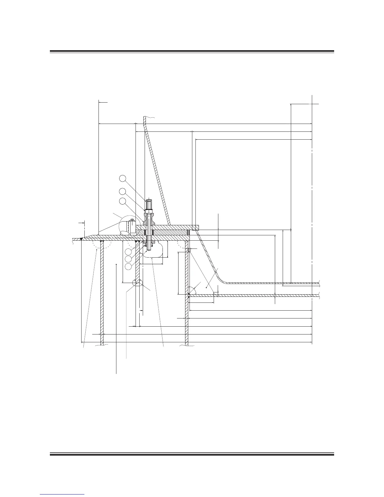
Fig. 5.12.02a : Profile of engine seating
Engine Seating Profile
Holding down bolts, option: 4 82 602 include:
1. Protecting cap
2. Spherical nut
3. Spherical washer
079 40 88-6.2.0a
4. Distance pipe
5. Round nut
6. Holding down bolt
Section A-A
160
220
Centreline engine
400
R30
1,132
1,100
1,665
533
350
+35
50 -25
50
1,190 to centreline crankshaft
510
529
56020
28
1,630
1,970
2,18 0
1,155
1,170
36
28
This space to be kept free from pipes etc. along both sides
of the engine in order to facilitate the overhaul work on
holding down bolts, supporting chocks and side chocks.
Thickness of floorplates
between main engine girders 22mm.
Continuous girder to extend with full dimensions
at least to ship's frame forward of engine and at
least to ship's frame aft of the aft end of end chock.
Corners of
floorplates
to be cut to
enable proper
welding of
girders. e.g.
as shown.
Slots to be cut in vertical floorplates
to clear nuts when necessary.
400
20
R75
240
20
If required by classification
society, apply this bracket.
Thickness of bracket is the
same as thickness of floorplates
D1
3
2
6
1
5
4
B
B
 Loading...


