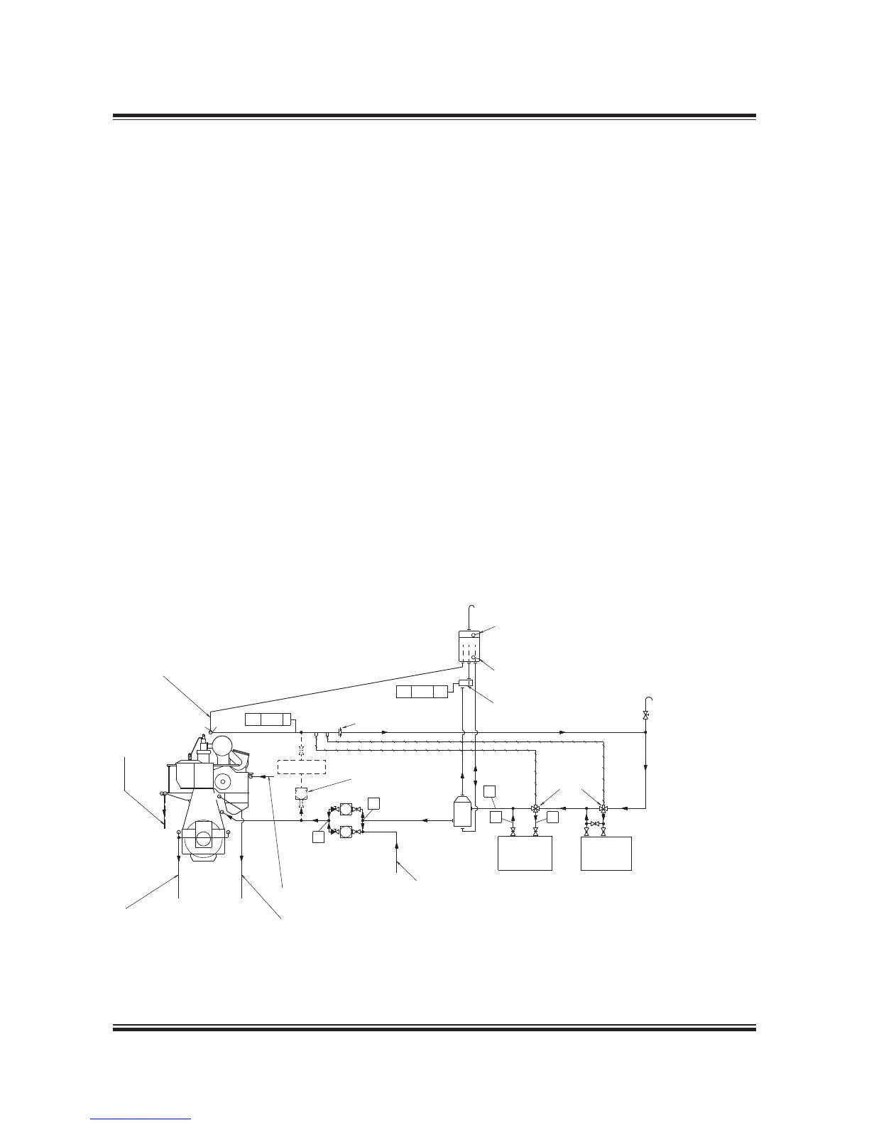
Expansion tank
Low level alarm
Alarm device box,
see Fig. 12.07.02
Normally closed valve.
To be opened when the
system is filled with
cooling water. (Manually
or automatically)
Freshwater
generator
Jacket water
cooler
Deaerating tank,
see Fig. 12.07.01
From tracing of fuel oil drain pipe
High level alarm
Regulating
valve
Preheater pump
Jacket Cooling Water System
The jacket cooling water system is used for cool-
ing the cylinder liners, cylinder covers and exhaust
valves of the main engine and heating of the fuel
oil drain pipes, see Fig. 12.05.01.
The jacket water pump draws water from the
jacket water cooler outlet and delivers it to the
engine.
At the inlet to the jacket water cooler there is a
thermostatically controlled regulating valve, with
a sensor at the engine cooling water outlet, which
keeps the main engine cooling water outlet at a
temperature between 88 and 92 °C.
The engine jacket water must be carefully treated,
maintained and monitored so as to avoid corro-
sion, corrosion fatigue, cavitation and scale for-
mation. It is recommended to install a preheater
if preheating is not available from the auxiliary
engines jacket cooling water system.
The venting pipe in the expansion tank should end
just below the lowest water level, and the expan-
sion tank must be located at least 15 m above the
top of the exhaust valves.
The freshwater generator, if installed, may be con-
nected to the seawater system if the generator
does not have a separate cooling water pump.
The generator must be coupled in and out slowly
over a period of at least 3 minutes.
In case it is possible to utilise more than 50% of
the heat available, we recommend to install a ther-
mostatic valve at the freshwater generator inlet,
adjusted to keep a minimum cooling water outlet
temperature of 88 °C.
For external pipe connections, we prescribe the
following maximum water velocities:
Jacket water ................................................ 3.0 m/s
Seawater ..................................................... 3.0 m/s
Fig. 12.05.01: Jacket cooling water system
078 70 71-7.0.1
The letters refer to list of ‘Counterflanges’
 Loading...


