MAN Diesel
MAN B&W S50MEC, G50ME-B, S50ME-B, S46ME-B,
S40ME-B, G40ME-B, S35ME-B, S30ME-B
198 76 610.4
Fuel Oil System
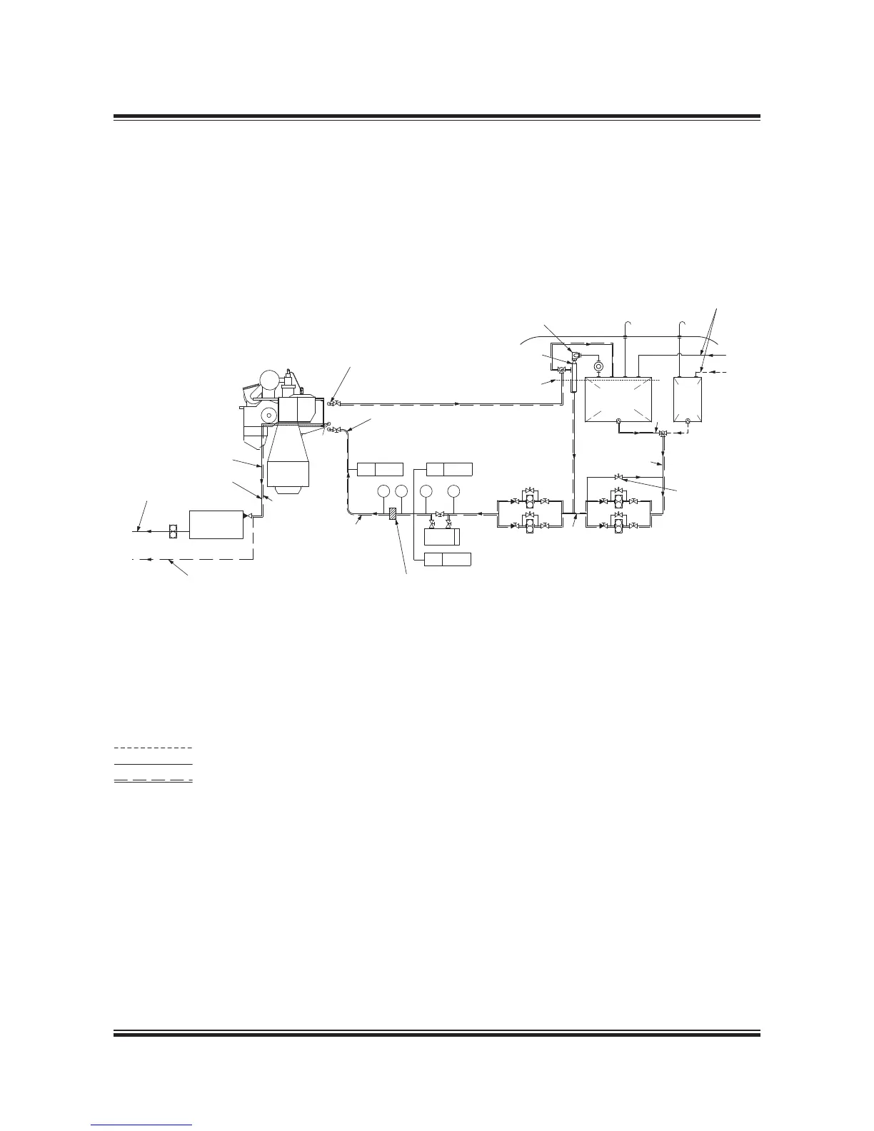
Fig. 7.01.01: Fuel oil system
078 70 06-1.1.0a
Diesel oil
Heavy fuel oil
Heated pipe with insulation
a) Tracing fuel oil lines: Max.150°C
b) Tracing drain lines: By jacket cooling water
The letters refer to the list of ‘Counterflanges’
Deck
PI TI
Heater
PI TI
From centrifuges
Circulating pumps Supply pumps
D* )
d* )
D* )
32 mm Nominal bore
Aut. deaerating valve
Top of fuel oil service tank
Venting tank
Arr. of main engine fuel oil system.
(See Fig. 7.03.01)
F
X
AF
#
)
b)
a)
BD
To storage/settling tank
To freshwater cooling pump suction
To drain tank
Fuel oil
drain tank
If the fuel oil pipe to engine is made as a straight line
immediately before the engine, it will be necessary to
mount an expansion unit. If the connection is made
as indicated, with a bend immediately before the
engine, no expansion unit is required.
Full flow filter.
For filter type see engine spec.
Overflow valve
Adjusted to 4 bar
Heavy fuel oil
service tank
Diesel
oil
service
tank
TE 8005
#) Approximately the following quantity of fuel oil should be treated in
the centrifuges: 0.23 l/kwh as explained in Section 7.05. The capacity of
the centrifuges to be according to manufacturer’s recommendation.
* ) D to have min. 50% larger passage area than d.
PT 8002
VT 8004
 Loading...


