Main Dimensions
Symbol Unit Ballast Loaded
Length between perpendiculars LPP m
Length of load water line LWL m
Breadth B m
Draft at forward perpendicular TF m
Draft at aft perpendicular TA m
Displacement o m3
Block coefficient (LPP) CB
Midship coefficient CM
Waterplane area coefficient CWL
Wetted surface with appendages S m2
Centre of buoyancy forward of LPP/2 LCB m
Propeller centre height above baseline H m
Bulb section area at forward perpendicular AB m2
178 22 970.0
Table 5.18.03: Data sheet for propeller design purposes, in case model test is not available this table should be filled in
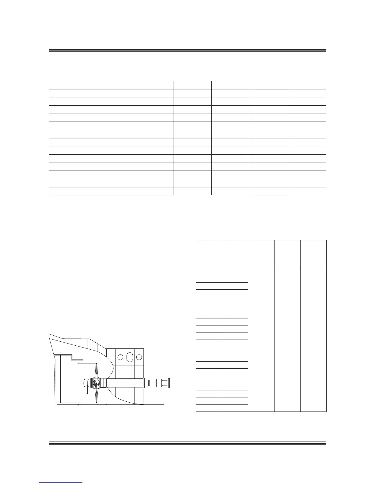
Propeller clearance
To reduce pressure impulses and vibrations emit-
ted from the propeller to the hull, MAN Diesel &
Turbo recommends a minimum tip clearance as
shown in Fig. 5.18.04.
For ships with slender aft body and favourable
inflow conditions the lower values can be used,
whereas full afterbody and large variations in
wake field cause the upper values to be used.
In twinscrew ships the blade tip may protrude
below the base line.
Hub
Dismant-
ling
of cap
X mm
High-skew
propeller
Y mm
Nonskew
propeller
Y mm
Baseline
clearance
Z mm
VBS 600 120
1520%
of D
2025%
of D
Min.
50100
VBS 660 130
VBS 720 140
VBS 790 155
VBS 860 170
VBS 940 185
VBS 1020 200
VBS 1100 215
VBS 1180 230
VBS 1260 245
VBS 1350 265
VBS 1460 280
VBS 1550 300
VBS 1640 320
VBS 1730 340
VBS 1810 355
VBS 1890 370
VBS 1970 385
VBS 2060 405
VBS 2150 425
216 56 93-7.3.1
Fig. 5.18.04: Propeller clearance
178 22 372.0
 Loading...


