MAN B&W 14.06
Page 1 of 1
MAN Diesel
MAN B&W 50MC-C/ME-C/ME-B/-GI 198 76 93-3.2
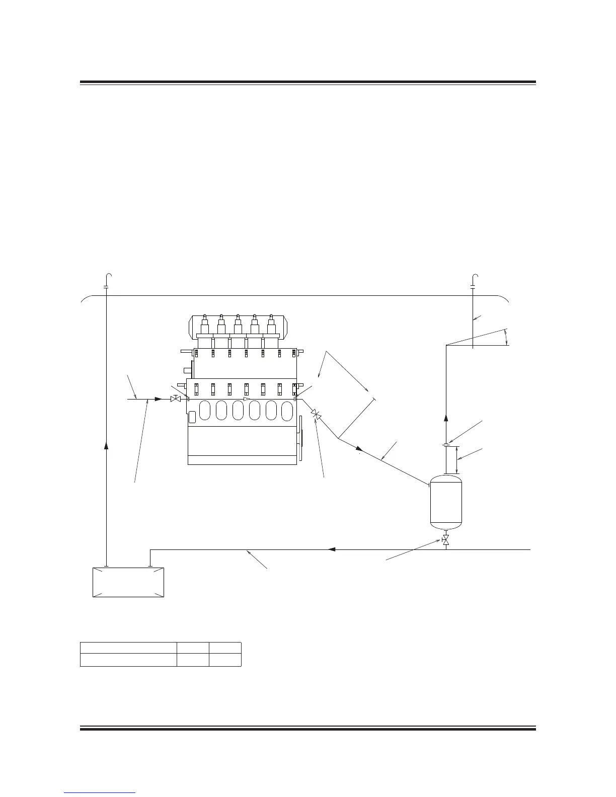
The scavenge air box is continuously drained
through ‘AV’ to a small pressurised drain tank,
from where the sludge is led to the sludge tank.
Steam can be applied through ‘BV’, if required, to
facilitate the draining. See Fig. 14.06.01.
The continuous drain from the scavenge air box
must not be directly connected to the sludge tank
owing to the scavenge air pressure.
Fig. 14.06.01: Scavenge air box drain system
The pressurised drain tank must be designed to
withstand full scavenge air pressure and, if steam
is applied, to withstand the steam pressure avail-
able.
The system delivered with and fitted on the engine
is shown in Fig. 14.03.02 Scavenge air space,
drain pipes.
079 61 03-0.4.1
Deck / Roof
Orifice 10 mm
DN=15 mm
BV
AV
Min. 15°
DN=50 mm
1,000 mm
DN=65 mm
DN=50 mm
AV1
Drain
tank
Normally open.
To be closed in case of
fire in the scavenge air box.
Steam inlet pressure 310 bar.
If steam is not available, 7 bar
compressed air can be used.
Sludge tank for fuel
oil centrifuges
Normally closed. Tank to be emptied
during service with valve open.
If the engine is equipped with both ‘AV’ and
‘AV1’ connections, these can be connected
to the drain tank.
The ‘AV’ and AV1’ connection can also be
connected to the drain tank separately.
The letters refer to list of ‘Counterflanges’
Scavenge Air Box Drain System
No. of cylinders:
5-6 7-9
Drain tank capacity, m
3
0.3 0.4
 Loading...


