MI 2893 / MI 2892 / MI 2885 Phase Diagram
65
Figure 46: Phase diagram screen
Table 35: Instrument screen symbols and abbreviations
Fundamental voltages Ufund
1
, Ufund
2
, Ufund
3
with relative phase angle to Ufund
1
Fundamental voltages Ufund
12
, Ufund
23
, Ufund
31
with relative phase angle to
Ufund
12
Fundamental currents Ifund
1
, Ifund
2
, Ifund
3
with relative phase angle to Ufund
1
or
Ufund
12
Table 36: Keys in Phase diagram screen
Holds measurement on display. Hold clock time will be displayed in the
right top corner.
Selects voltage for scaling (with cursors).
Selects current for scaling (with cursors).
Switches to PHASE DIAGRAM view.
Switches to UNBALANCE DIAGRAM view.
Switches to TREND view (available only during recording).
Scales voltage or current phasors.
Triggers Waveform snapshot.
Returns to the “MEASUREMENTS” submenu.
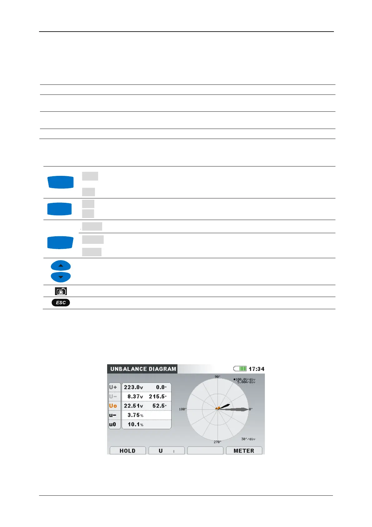
3.10.2 Unbalance diagram
Unbalance diagram represents current and voltage unbalance of the measuring system. Unbalance
arises when RMS values or phase angles between consecutive phases are not equal. Diagram is shown
on figure below.
Figure 47: Unbalance diagram screen