MI 2893 / MI 2892 / MI 2885 General Recorder
74
0 – none of intervals are flagged
1 – at least one of intervals inside recorded signalling is
flagged
Frequency on which signalling occurred, defined as “Sign. 1”
frequency (f1) and “Sign. 2” frequency (f2) in SIGNALLING SETUP
menu. See 3.23.4 for details.
Time when observed Signalling voltage crosses threshold boundary.
Maximal voltage level recorder captured during signalling events
Threshold level in % of nominal voltage Un, defined in SIGNALLING
SETUP menu. See 3.23.4 for details.
Duration of captured waveform, defined in SIGNALLING SETUP
menu. See 3.23.4 for details.
1
st
observed signalling frequency.
2
nd
observed signalling frequency.
Table 54: Keys in Signalling (TABLE) screen
Switches to TREND view (available only during recording).
Switches to TABLE view (available only during recording).
Moves cursor through signalling table.
Returns to the “MEASUREMENTS” submenu.
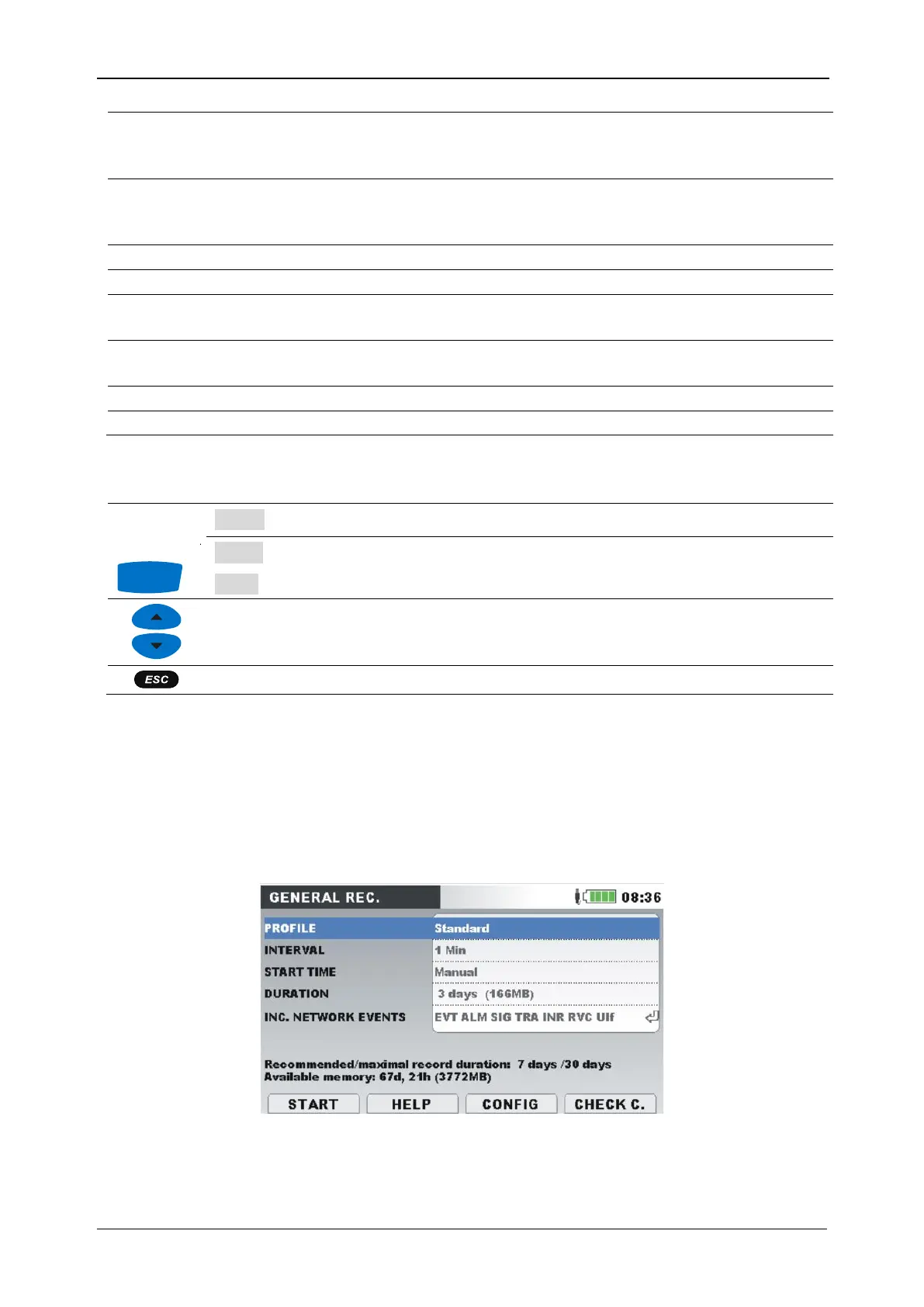
3.14 General Recorder
MI 2893/MI 2892/MI 2885 has ability to record measured data in the background. By entering GENERAL
RECORDER option from RECORDERS submenu, recorder parameters can be customized in order to meet
criteria about interval, start time and duration for the recording campaign. General recorder setup
screen is shown below:
Figure 56: General recorder setup screen
Description of General recorder settings is given in the following table: