MI 2893 / MI 2892 / MI 2885 Signalling
71
Selects between the following options:
Shows under deviation trends
Shows over deviation trends
Selects between trending various parameters:
Shows trends for all phase under/over deviations
Shows trends for all lines under/over deviations
Switches to TREND view (available only during recording).
Moves cursor and selects time interval (IP) for observation.
Returns to the “MEASUREMENTS” submenu.
3.13 Signalling
Mains signalling voltage, called “ripple control signal” in certain applications, is a burst of signals, often
applied at a non-harmonic frequency, that remotely control industrial equipment, revenue meters, and
other devices. Before observing signalling measurements, user should set-up signalling frequencies in
signalling setup menu (see section 3.23.4).
Results can be seen in a tabular (METER) or a graphical form (TREND) - which is active only while
GENERAL RECORDER is active. See section 3.14 for instructions how to start recording. In order to
understand meanings of particular parameter see section 5.1.9.
3.13.1 Meter
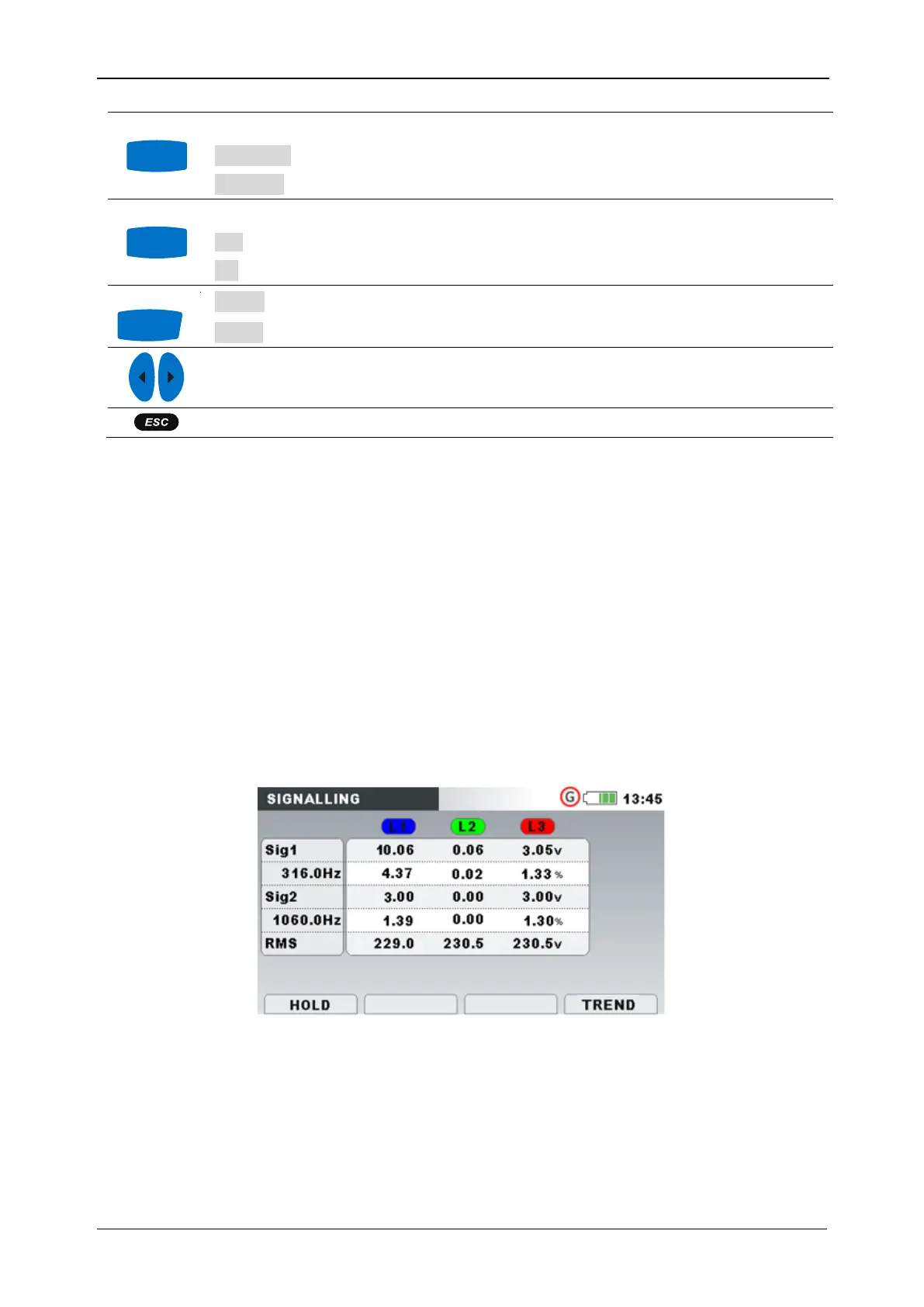
By entering SIGNALLING option from MEASUREMENTS submenu, the SIGNALLING tabular screen is
shown (see figure below).
Figure 53: Signalling meter screen
Description of symbols and abbreviations used in METER screen is shown in table below.
Table 49: Instrument screen symbols and abbreviations