Operation and Menu Structure 31
_______________________________________________________________________________________________
________________________________________________________________________________________________
MICROPLEX Operator’s Manual SOLID F90 HD Edition 1.0
4. Operation and Menu Structure
4.1. Attaching the Printer to a Computer
1. Make sure the printer, computer, and any other attached devices
are turned off and unplugged.
2.
Use a proper interface line to connect the printer to the computer or to
attach the printer to the network.
The printer SOLID F90 HD is provided with several interfaces; see
chapter 10 Specifications for more information.
4.2. Printer Power on
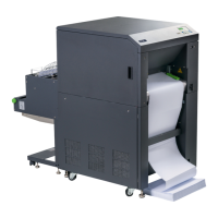
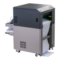
The power switch is located at the right side of the printer (see section 2.3
Printer Components). As soon as the printer’s warm up phase is finished the
print system SOLID F90 HD goes into the ON LINE mode.
The Online LED and the Ready LED shine and the name of the printer is
displayed.