Physical Views Product Description
1 - 16 046-003777-00 A5/A3™ Operating Instructions
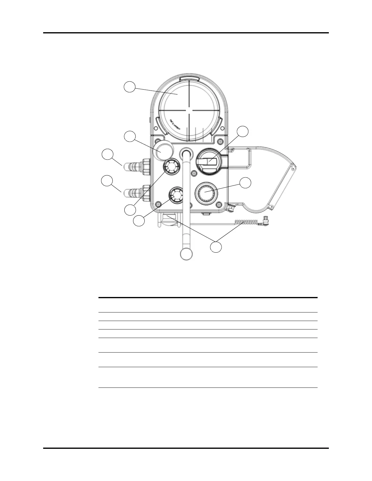
1.2.6 Breathing System (Top View)
FIGURE 1-7 Breathing System (Top View)
PART(S) DESCRIPTION
F1 Bellows (including bellows
dome)
1
Bellows that separates the breathing system gases from the
oxygen drive gas
F2 PAW Gauge
2
Indicates the patient airway pressure
F3 Expiratory Limb Exhaled breathing circuit connection
F4 Inspiratory Limb Inhaled breathing circuit connection
F5 Expiration Valve Allows flow of expiratory gas from the patient to the re-
breathing system, and prevents reverse flow.
F6 Inspiration Valve Allows flow of inspiratory gas to the patient, and prevents
reverse flow.
F7 O
2
Sensor Cable Assembly An electro-galvanic fuel cell device to measure the
concentration of O
2
. The assembly is composed of the O
2
cable, O
2
cell cover, and O
2
sensor.
1
The bellows dome is a transparent cover with graduation marks from 300 to 1500 ml. These marks are for ref-
erence only. Tidal volume (Vt) should be read exclusively from the display of the user interface. Delivered Vt is
a combination of bellows displacement and fresh gas flow.
2
The APL valve and PAW gauge numerics are for reference only. Calibrated patient airway pressure is dis-
played on the user interface.