A5/A3™ Operating Instructions 046-003777-00 1 - 13
Product Description Physical Views
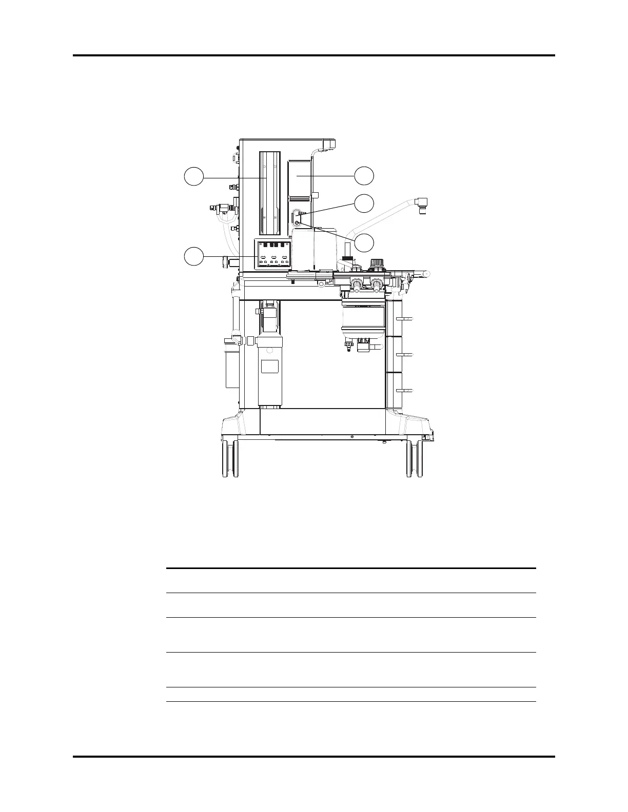
1.2.3 Main Unit (Left View)
FIGURE 1-4 Main Unit (Left View)
PART(S) DESCRIPTION
C1 Auxiliary O
2
/Air
Flowmeters
Auxiliary O
2
/Air Flowmeters for auxiliary O
2
/Air output
C2 Auxiliary O
2
/Air Gas
Outlet
Nozzle (barbed connector) for auxiliary O
2
/Air output. Combines the
auxiliary O
2
/Air flowmeters into a single output.
C3 Auxiliary O
2
Gas
Power Outlet
(A5 only)
High pressure O
2
outlet (DISS connector) for connecting external
devices such as a jet ventilator.
C4 Rail Mount Enables mounting of patient monitors and most standard attachment
arms for other devices. Rail mounts are on both left and right sides of
the A5/A3.
C5 Module slot AG module can be inserted into the slot and identified.