Physical Views Product Description
1 - 20 046-003777-00 A5/A3™ Operating Instructions
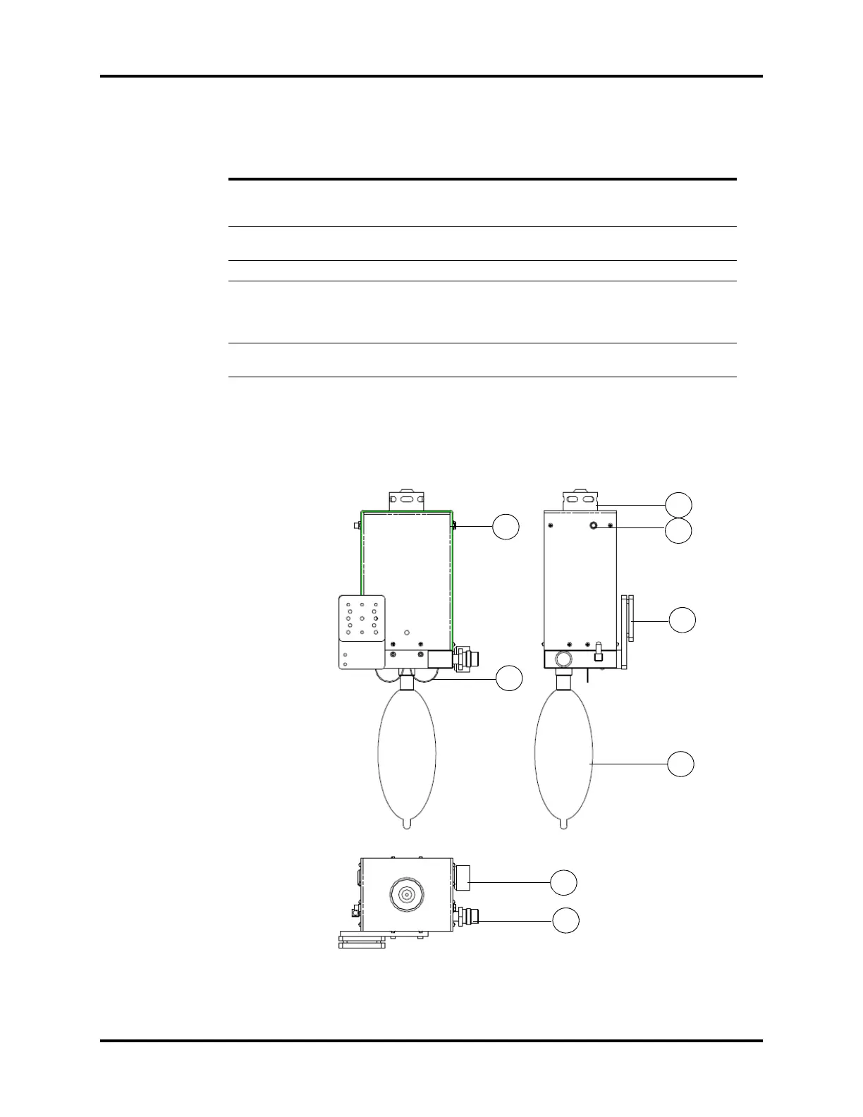
1.2.8.2 Dynamic Gas Scavenging System (DGSS) (Top, Right, and Rear
Views)
FIGURE 1-11 DGSS (Top, Right, and Rear Views)
PART(S) DESCRIPTION
H1 Mounting Rail Attachment Allows the AGSS to be mounted on the side rail. Contains a
thumbscrew that must be tightened against the mounting
rail.
H2 Flow Adjust Knob Turn clockwise or counter-clockwise to adjust the flow in the
AGSS until the float is between Min and Max marks.
H3 Exhaust Port Exhaust port to the hospital’s waste gas scavenging system.
H4 Inlet Port Intake for exhaust gases from the breathing system. The
waste gas transfer hose connects the inlet port and the waste
gas scavenging connector (see
FIGURE 1-3) to transfer the
exhaust gases.
H5 Float Indicates exhaust flow. Adjusted by turning the Flow Adjust
Knob (H2) until the float is between the Min and Max marks.
Rear View
Right View
Top View
I1
I2
I3
I4
I5
I6
I7
I8