14-5
2. Connect the ICP adapter cable, measurement module, and the target monitor, or insert the measurement module
into the target monitor.
3. Check that the zero reference value displayed on the monitor is consistent with that recorded on the ICP
transducer.
Consistent: select [Accept].
Inconsistent: input the zero reference value recorded on the ICP transducer, and select [Accept].
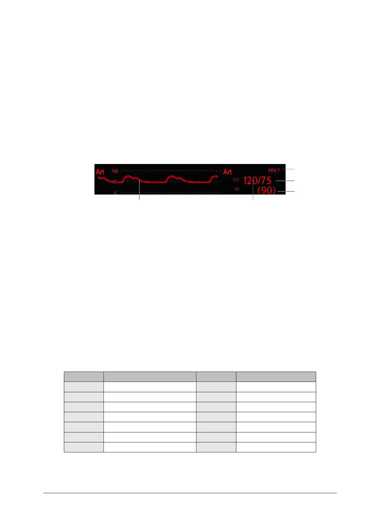
14.5 Understanding the IBP Display
The IBP measurement is displayed on the monitor as a wavef
orm and numeric pressures. The figure below shows the
waveform and numerics for the Art pressure. For different pressures, this display may be slightly different.
1. Waveform
2. Systolic pressure
3. Mean pressure
4. Diastolic pressure
5. PPV measurement
For some pressures, the parameter window may show the mean pressure only. For different pressures, their defaults unit
may be different. If the Art and ICP pressures are measured simultaneously, the ICP parameter area will display numeric
CPP, which is obtained by subtracting ICP from the Art mean.
14.6 Changing IBP Settings
14.6.1 Ch
anging a Pressure for Monitoring
1. Select the pressure you want to change to enter its setup menu.
2. Select [Label] and then select your desired label from the list. The already displayed labels cannot be selected.
Label Description Label Description
PA Pulmonary artery pressure CVP Central venous pressure
Ao Aortic pressure LAP Left atrial pressure
UAP Umbilical arterial pressure RAP Right atrial pressure
BAP Brachial arterial pressure ICP Intracranial pressure
FAP Femoral arterial pressure UVP Umbilical venous pressure
Art Arterial blood pressure LV Left ventricular pressure
CPP Cerebral perfusion pressure P1 to P4 Non-specific pressure label
1
2
4
3
5