EasyManuals Logo

Mindray uMEC12 Operator's Manual

Mindray uMEC12
288 pages
To Next Page IconTo Next Page
To Previous Page IconTo Previous Page
Page #93 background imageLoading...
Page #93 background image
8-3
8.3.3 ECG Lead Placements
The electrode placement illustrations in this chapter adopt the AHA standard.
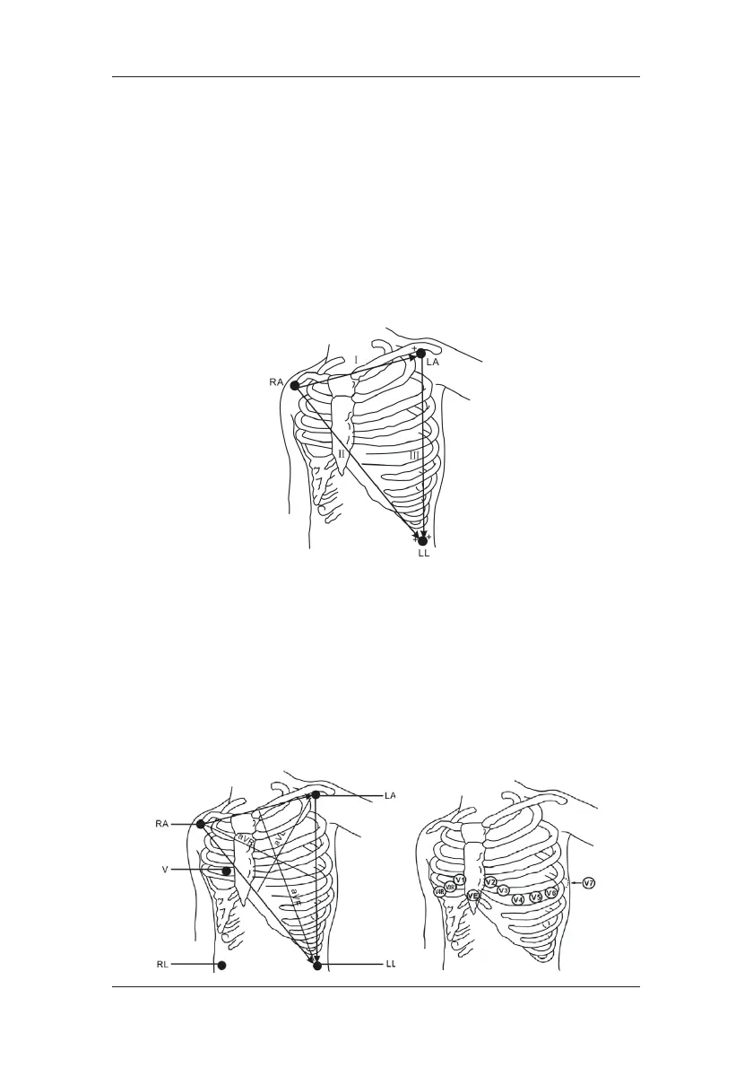
3-Leadwire Electrode Placement
Following is an electrode configuration when using 3 leadwires:
 RA placement: directly below the clavicle and near the right shoulder.
 LA placement: directly below the clavicle and near the left shoulder.
 LL placement: on the left lower abdomen.
5-Leadwire Electrode Placement
Following is an electrode configuration when using 5 leadwires:
 RA placement: directly below the clavicle and near the right shoulder.
 LA placement: directly below the clavicle and near the left shoulder.
 RL placement: on the right lower abdomen.
 LL placement: on the left lower abdomen.
 V placement: on the chest.

Table of Contents

Other manuals for Mindray uMEC12

Questions and Answers:

Question and Answer IconNeed help?

Do you have a question about the Mindray uMEC12 and is the answer not in the manual?

Mindray uMEC12 Specifications

General IconGeneral
TypePatient Monitor
Display12.1-inch color TFT
ECG3-lead
SpO2Yes
NIBPYes
RespirationYes
TemperatureYes
BatteryRechargeable lithium-ion
NetworkingEthernet
ParametersECG, SpO2, NIBP, Respiration, Temperature
ConnectivityEthernet
Battery LifeUp to 4 hours
Power Supply100-240 VAC, 50/60 Hz

Related product manuals