23
Kaleido-X
User’s Manual
These inputs allow the multiviewer to connect to external serial devices such as a router,
production switcher, or router controller.
The pinout for the RS-422 signals at the RJ-45 connectors on a Kaleido-X16—or on the
output cards’ rear panel, in the case of a Kaleido-X—, and the wiring diagrams for the
appropriate adapters, are shown here:
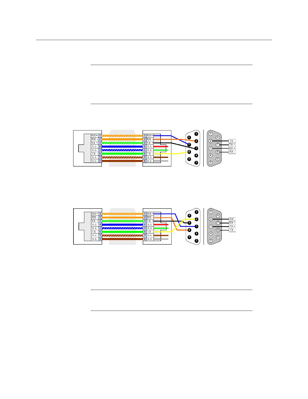
Standard wiring between multiviewer and devices wired to SMPTE “slave” specification (e.g. most
routers, Ross Synergy switchers, Nevion ETH-CON)
Standard wiring between multiviewer and devices wired to SMPTE “master” specification (e.g. Philips
Jupiter router control system, Miranda Presmaster PCS)
Note: The RS-422 ports each have an RJ-45 connector in order to preserve
space on a busy panel. The RS-422 interface specifies a DE-9 connector, so if
you are using this interface, you will require a DE-9-to-RJ-45 adapter.
Miranda supplies two adapter models, correctly wired for this application: a
straight adapter (part no. 1737-3000-102), and a crossover adapter (part no.
1792-3700-100).
Note: The two RS-422 ports on the multiviewer side have no ground pin.
Using the appropriate DE-9S-to-RJ-45 adapter, an external device should be
able to communicate with a multiviewer despite the lack of a ground.
Pinout of each RS-422
port’s RJ-45 connector
on the multiviewer
Pinout of straight adapter
(Miranda part no. 1737-3000-102)
RJ-45 DE-9 male DE-9 female
Pinout of RS-422
connector on SMPTE
slave device
Pinout of each RS-422
port’s RJ-45 connector
on the multiviewer
RJ-45 DE-9 male DE-9 female
Pinout of crossover adapter
(Miranda part no. 1792-3700-100)
Pinout of RS-422
connector on SMPTE
master device