PRO-2000 Installation and Operation Manual
15
PRO-2000 X6 Common Features
The X6 Series supports communication and networking functions. The X6 can operate as a stand-alone panel or
it can be networked in a master/slave configuration. The master can be configured to monitor and control the
slave panels as well as monitor its own devices.
The X6 panels can support communication to one RS-232 and one repeater network using small communication
modules. By adding an RS-232 communication module to the MPU card, the X6 panels can communicate with
external devices, such as printers or computers, via a standard modular phone jack. The RS-232 communication
module supports one channel. The built-in RS-422 communication module enables X6 panels to support a
maximum of two Repeater networks. The RS-422 communication module supports 2 channels. For enhanced
networking capabilities, Communication interface cards can be added to the panel.
The printer used must be UL Listed (ULC Listed in Canada).
The X6 panels can accept up to 6 of the following expansion cards:
• Addressable Detector Interface (ADI) card - smoke/heat detectors, monitor modules, control modules, and 4
onboard supervised/unsupervised outputs
• 24/32 Zone Supervised Input (S1) card - conventional detectors, shorting and non-shorting devices
• 12 Zone Supervised OUTPUT (SO) card - supervised outputs and dry contacts
• Communication Card - networked configurations
General Installation Guidelines
The panel should be installed in a dry, clean, well lit and secured area. No combustible or hazardous material
should be stored in the vicinity of the installed unit. The installation must comply with all local and/or national
regulations and codes of practice governing fire alarm system installation, electrical wiring, life safety, etc.
Special Handling
Circuit cards are to be stored in anti-static packaging and kept away from the sun and from direct sources of
intense UV light. The circuit card may be subject to degradation due to electrostatic discharge; therefore
grounding straps must be worn when handling the cards.
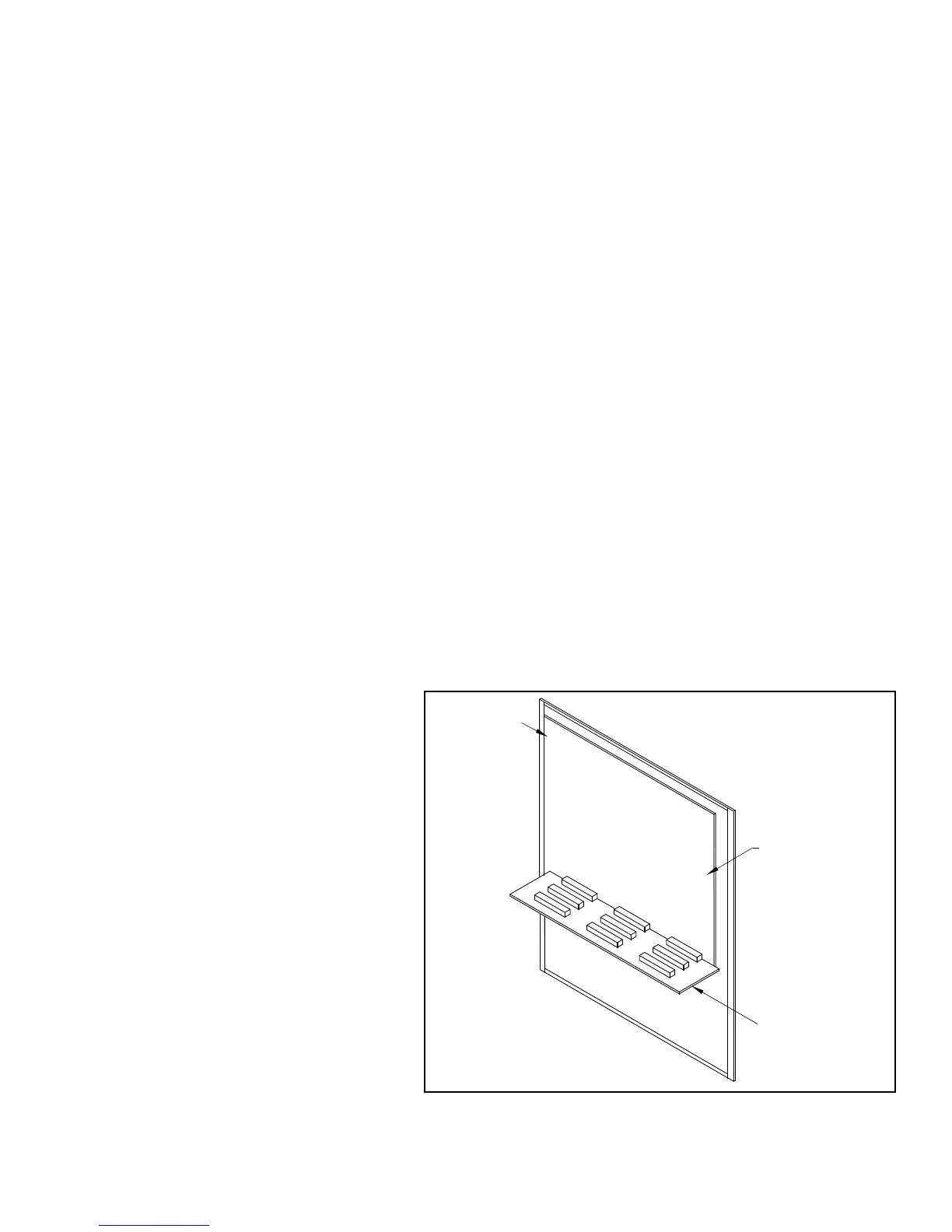
Enabling the Onboard Lithium
Battery Backup
The X6 panels are shipped with the jumper for the
lithium battery disconnected. You must insert the
jumper to activate the battery backup for the real
time clock and the RAM memory used for the
event log. Jumper is located on the MPU (JP3).
Cable Entry and Internal
Routing
On the enclosure there are two removable cable
entry plates. These plates are to be removed,
punched, and re-installed. For additional entry
holes, outside the cable entry plates:
1. Disconnect the wiring harness from the
MPU to the LCD card.
2. Disconnect the door ground strap and
remove the enclosure door with
attached electronics from the enclosure
base.
3. Remove the mounting plate with the
attached electronics from the enclosure base.
MPU CCA
LITHIUM
MPU BACKPLANE
JUMPER
BATTERY
Figure 10: Micro-processor (MPU)