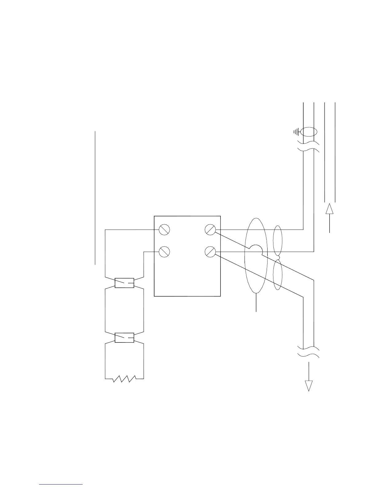
FROM LAST MODULE/DETECTOR
MODULE
MONITOR
EOL Resistor is supplied with the Monitor Module
CIRCUIT SUPERVISED AND POWER-LIMITED
AND VOLTAGE LIMITED TO 12V MAX.
LIMITED TO 230 MICRO AMPS MAX
TERMINALS 6 & 7 ARE CURRENT
*
(loop mode)
connections
addressable
To ADI card
NOTES:
loop
LPX-
LPX+
LPY-
LPY+
(-)
(+)
6
(+)
7
(-)
M500M
SHIELDED, TWISTED PAIR
2
1
47K EOLR
*
POWER-LIMITED CIRCUITS
DEVICE
NEXT
TO
Figure 47: 2 Wire Class B Initiating Circuit Configuration of Monitor Module