PRO-2000 Installation and Operation Manual
49
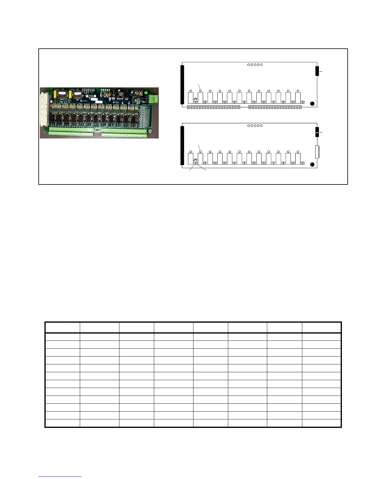
12 Zone Supervised OUTPUT Card
The SO card supports 12 supervised outputs or 12 dry contacts (Form C). The card's 12 relays have jumpers to
determine if the outputs are supervised or not.
There are two versions of this card. It can either come with screw terminal connections or a DSUB connector. The
screw terminal connections allow more current load and should be used for high power outputs. The DSUB
connector version is limited in current handling but is easier to use when wiring a large number of outputs.
Supervision circuits use an external power supply (24V) isolated from the main power supply of the card. The
power supply should be regulated and UL Listed for Fire Protective Signaling Systems (ULC Listed in Canada),
battery backed-up, and fully supervised. The metallized Ground on the card provides the path to chassis for
transient protection.
To use dry contacts, no external power is required. The supervised jumper and power jumper should be removed.
To activate supervision circuits of the Supervised OUTPUT card, an external power supply must be connected to
the External Power Connector. To configure each individual OUTPUT as supervised, insert the supervised jumper
and remove the power jumper for that output.
Signal Connection Signal Connection Signal Connection Signal Connection
SO1-NO J2-1 SO4-NO J2-13 SO7-NO J3-1 SO10-NO J3-13
SO1-NC J2-2 SO4-NC J2-14 SO7-NC J3-2 SO10-NC J3-14
SO1-COM J2-3 SO4-COM J2-15 SO7-COM J3-3 SO10-COM J3-15
GND J2-4 GND J2-16 GND J3-4 GND J3-16
SO2-NO J2-5 SO5-NO J2-17 SO8-NO J3-5 SO11-NO J3-17
SO2-NC J2-6 SO5-NC J2-18 SO8-NC J3-6 SO11-NC J3-18
SO2-COM J2-7 SO5-COM J2-19 SO8-COM J3-7 SO11-COM J3-19
GND J2-8 GND J2-20 GND J3-8 GND J3-20
SO3-NO J2-9 SO6-NO J2-21 SO9-NO J3-9 SO12-NO J3-21
SO3-NC J2-10 SO6-NC J2-22 SO9-NC J3-10 SO12-NC J3-22
SO3-COM J2-11 SO6-COM J2-23 SO9-COM J3-11 SO12-COM J3-23
GND J2-12 GND J2-24 GND J3-12 GND J3-23
Table 14: 12 Zone Supervised OUTPUT Card Pin outs - Screw Termination
J4
Metalized
Ground
Power Indicators
Connector to
MPU or LCD
Power Supply
External
LD1 LD5
J2 J3
11
Screw Connectors for Field Connections
Output Status
Indicator
LD6
LD17
JP25
LD6
JP25
Metalized
Ground
LD17
Power Indicators
LD1 LD5
External
Power Supply
J4
J5
SUBD Connector
for
Field Connections
Relays
Relays
Supervised
Jumper
Power
Jumper
Connector to
MPU or LCD
Indicator
Output Status
Figure 37: 12 Zone Supervised Output Card