Operating Conditions
76
Device ID Concepts
The Device ID is a special code used by the system to identify all the devices connected to the PRO-2000. In certain menus it is
required to identify a certain device Group to the system. For example, when placing/removing a device/device Group in/from Service
or Isolate modes. The following identifies the different fields of the Device ID:
AA-BBCD-EFFF.G
where:
• Field A is the Node number - A number identifying a specific panel. This number is a node address and is assigned when the
system is configured.
• Field B is the Slot number - A number identifying the expansion card to which the device is connected. Slot 00 has a special
meaning and refers to devices on the MPU for the X6 Series or on the Processing and Display Unit (LCD) for the X2 Series.
• Field C is the Line type - A letter identifying whether the device is connected to a Stub or a Loop.
• Field D is the Line Number - A number identifying the Stub/Loop.
• Field E is the Device type - A letter identifying the type of the Device, for example:
F: Thermal detector V: Virtual device
N: Ionization detector H: Hardware fault
S: Photoelectric detector K: Cable break
M: Monitor module P: Push button
C: Control module L: LCD Panel LED
D: ACDI module R: ADI Supervised output
#: All devices I: Supervised Input device
B Omni Detector O: Supervised OUTPUT device
E Laser Detector A: Card fault
• Field F is the Device address - An identification of the device on the Stub or Loop.
• Field G is the Device point - A decimal point and number value identifying a specific device function. For example, for an
addressable module connected to the ADI card, 0 represents a module (monitor, control, or ACDI), or 1 for a detector.
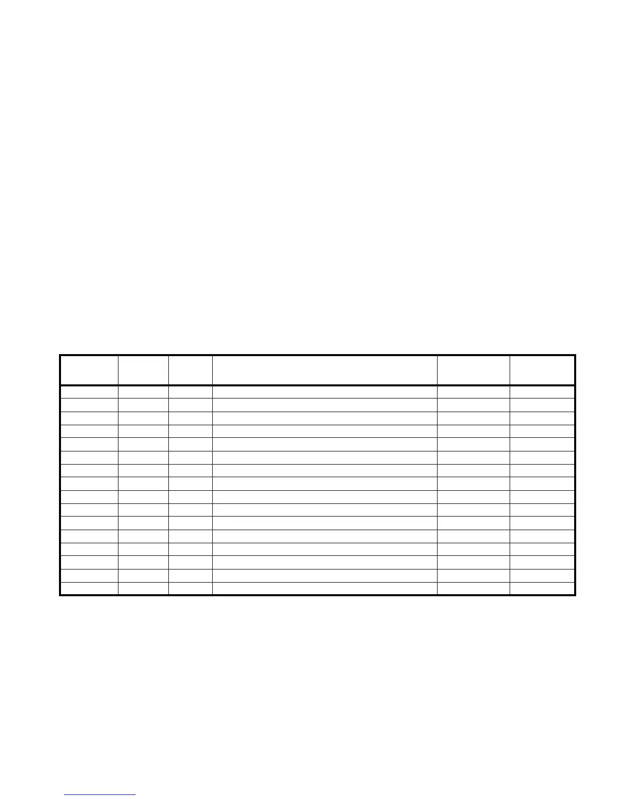
The 06/02 in the table refer to slots in the X6 and X2 Series panels.
Slot
Line
Type
Line # Device Type
Device
Address
Device
Point
00 S 0 to 9 V = Virtual Device 0 to 99 0 to 9
00 S 1 P = Push buttons 1 to 84 1
00 S 1 L = LCD panel LEDs (red and yellow) 00 to 22 0 to 7
00 to 06/02 S 1 H = Hardware fault
00 to 06/02 K = Cable break
00 to 06/02 A = Card fault
01 to 06/02 * * I = Supervised Input device 1 to 32 0
01 to 06/02 * * O = Supervised OUTPUT device 1 to 12 0
01 to 06/02 S/L 1 to 4 M = Monitor module 1 to 99 0
01 to 06/02 S/L 1 to 4 N = Ionization detector 1 to 99 1
01 to 06/02 S/L 1 to 4 S = Photoelectric detector 1 to 99 1
01 to 06/02 S/L 1 to 4 F = Thermal detector 1 to 99 1
01 to 06/02 S/L 1 to 4 C = Control Module 1 to 99 0
01 to 06/02 S/L 1 to 4 B = Omni detector 1 to 99 1
01 to 06/02 S/L 1 to 4 E = Laser Detector 1 to 99 1
01 to 06/02 S 5 R = ADI Supervised output 1 to 4 0
Table 30: PRO-2000 - Device ID