MAIN PROCESSING CARDS
34
MAIN PROCESSING CARDS
There are two main processing cards, the MPU and the LCD. These cards form the basis for the PRO-2000 Panels'
electronics.
In the X6 panels, the MPU card with the MPU Backplane, expansion cards (optional), Power Supply and
Transformer are mounted to a removable mounting plate in the enclosure base. The LCD card is mounted directly
on the enclosure door.
In the X2 Series the power supply and transformer are mounted to a removable mounting plate in the enclosure
base. The LCD with the LCD Backplane and optional expansion cards are mounted on the enclosure door.
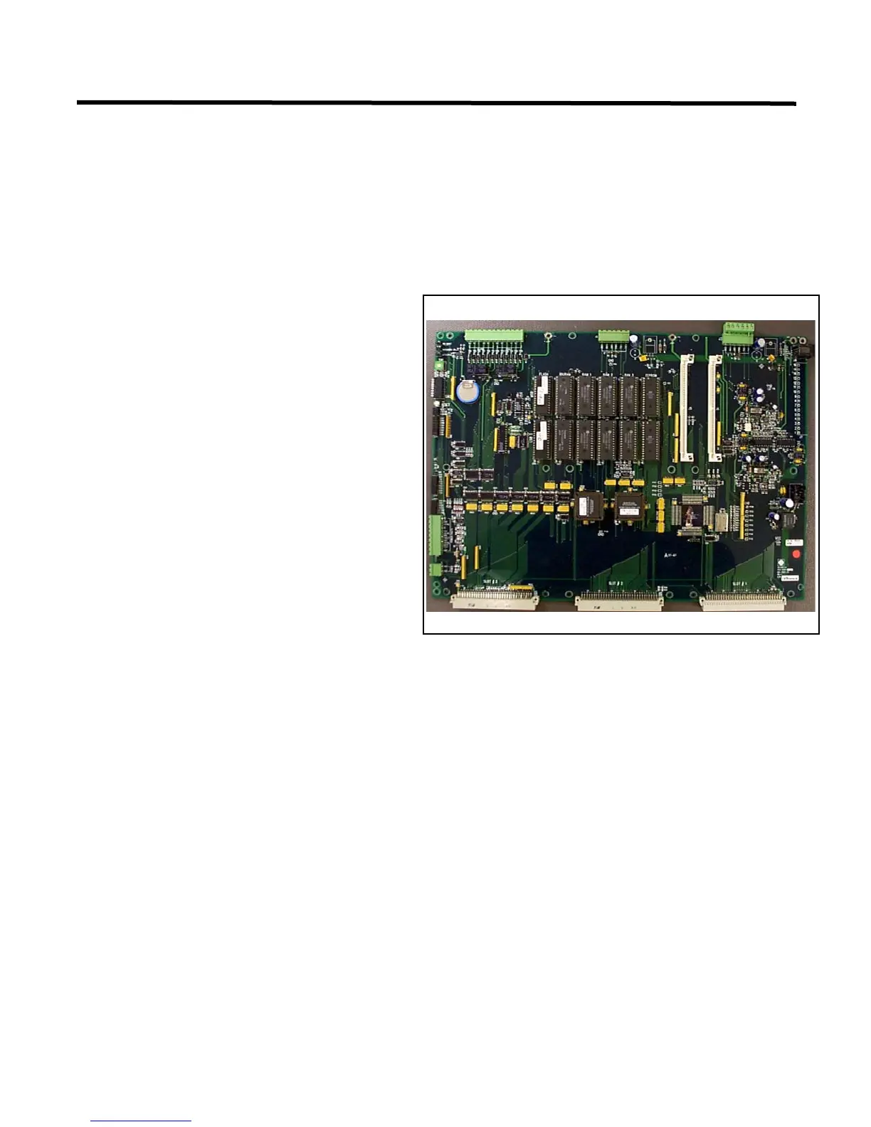
MPU - Main Processing Unit card
The Main Processing Unit (MPU) provides
processing and communication circuitry for the
X6 series panels. It provides two RS-422 full-
duplex, 4-conductor serial links used for
communications with the local LCD panel.
The MPU is shipped pre-installed on the
enclosure backplate with an MPU Backplane
attached and an, RS-422 communication module
installed. The MPU Backplane enables the MPU
to have up to 6 expansion cards installed, for
example, the ADI, Supervised output, or
Supervised Input cards. The MPU Backplane has
a side connector to plug into the MPU expansion
slot providing connectivity between the MPU and
the expansion cards.
The MPU provides monitoring of the power
supply for AC/DC fault detection. The card
provides the following visual indicators and
controls:
• Various status LEDs provide a visual indication of the card's health. There are Red LEDs for error codes,
blinking LEDs (Running) indicating the board is working; Green Power LEDs, and Communication LEDs.
• Reset push button to hard reset the MPU card.
• DIP switch providing software options. Factory set only.
• Rotary switch allowing the selection of different configuration modes. Factory set only.
• Three jumpers, two for the watchdog and one for battery. These jumpers must be connected at all times. A
watchdog circuit, monitoring microprocessor, halts system operation if a hardware or software failure occurs.
The lithium battery provides the backup for the real-time clock and the RAM memory used for event logging.
The real-time clock provides time and date for event recording.
Figure 26: MPU (Main Processing Unit) Card