MAIN PROCESSING CARDS
36
When a system is first delivered the MPU card has its internal battery jumper, JP3, disabled. Prior to installation,
move the jumper shunt (located above the board mounted battery) into position over both pins. If the jumper is
missing, the panel will annunciate a "Clock Battery Fault “ at power up. If the jumper is in, you can remove power
and the event log and the clock remain powered.
The MPU has two sockets for adding communication modules. Depending on your configuration, these could be
either the RS-232 or RS-422 communication modules. Installing an RS-232 module activates the phone jack
allowing MPU software configuration through an external PC or communication with a printer (depending on
position of SW1, see Table 4 below).
Installing an RS-422 module activates the two connectors to the LCD. The two connectors provide power to the
LCD. This available power is current limited to 1 amp. Note-the MPU ships with a pre-installed RS-422 module.
The MPU has built-in Common Alarm and Fault Relay-2 Form-C contacts for each relay. The Common Alarm Relay
activates whenever an alarm is present on the system. The Common Fault Relay activates whenever a fault is
present on the system. The rating for Common Alarm and Fault Relay is 2A at 30VDC.
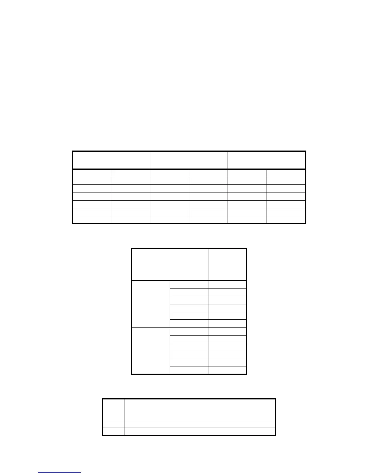
COMM Loop (S1 (J2) X) COMM Loop (S2 (J3) Y)
RS-232 Modular Phone
Jack (J4)
Signal Pin Signal Pin Signal Pin
TX1+ (out) 1 TX2+ (out) 1 TX (out) 5
TX1- (out) 2 TX2- (out) 2 RX (in) 2
24V 3 24V 3 RTS* (out) 3
GND4GND4CTS* (out)6
RX1+ (in) 5 RX2+ (in) 5 CD* (in) 1
RX1- (in) 6 RX2- (in) 6 GND 4
Table 2: MPU Pinouts
Common Alarm and
Trouble Relays (J1)
2A max @ 30V DC
Resistive
Pin
Trouble
C1 1
NC1 2
NO1 3
C2 4
NC2 5
NO2 6
Alarm
C1 7
NC1 8
NO1 9
C2 10
NC2 11
NO2 12
Table 3: MPU Relays
SW1
0: Printer, 1: Configuration, 2: Normal/Diagnose; 3: ModBus,
4: LCD, 5: Network, 6: Redundant, E: Firmware upgrade,
F: Default configuration
SW2 Normal position: All OFF
SW3 Used to reset the MPU card
Table 4: MPU Switches