PRO-2000 Installation and Operation Manual
47
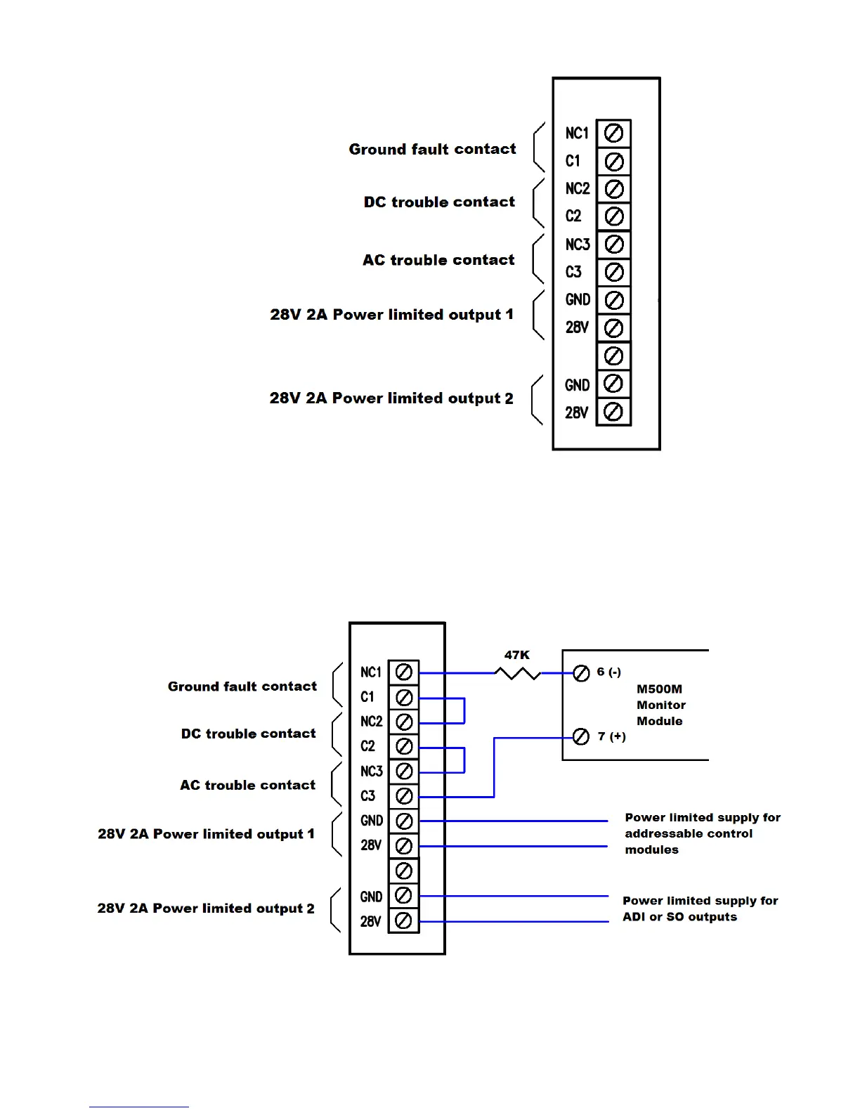
Typical connection for APS-14127-00 auxiliary power supply is shown in next figure. In this scheme, s single monitor
module is used for picking up trouble information from the auxiliary supply. If individual trouble reporting is required,
use a single monitor module per trouble contact.
See sections on ADI and SO cards for further details for power connections.
Figure 35: APS-14127-00 Auxiliary Power Supply Typical
Figure 34: APS-14127-00 Auxiliary Power Supply Connector