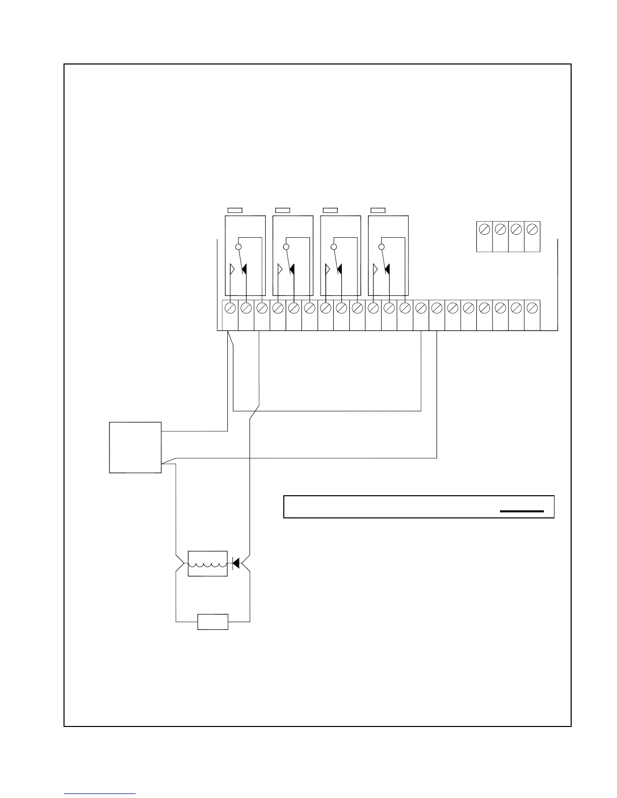
Max. current load (per relay circuit): 2A
Nominal voltage: 24 VDC
signaling devices.
Use only UL listed (ULC in Canada)
relay to be supervised.
Jumper to be installed for each
JP6
NOTES:
3.
2.
1.
RELAY 3
RELAY 4
RELAY 2
JP4
JP3
RELAY 1
JP5
(NOTE 2)
SUPPLY
POWER
24VDC
(+) (-)
Note 4
For NAC ciruits use MP-300SP end
of line mounting plate where required.
For selenoids ciruits use MP-320SP
end of line mounting plate where required
4.
(-)
Note 3
EOL
SUPERVISED, POWER-LIMITED CIRCUIT
(+)
VIN+
1
2
4
3
LPY1+
VOUT+
VIN-
VOUT-
LPX1-
LPX1+
LPY1-
NC2
NO2
NC1
NO1
2
1
3
4
5
C1
13
NO4
NC4
NC3
NO3
9C3
6
7
8
C2
11
10
12 C4
17
15
14
16
18
20
19
ADI CARD
J6
J7
Minimum detected ground fault impedance is 1K ohms.
Use only UL Listed for Fire Protective Signaling Systems
(ULC Listed in Canada) regulated, isolated 24VDC power
supply (supervised and power limited).