MAIN PROCESSING CARDS
44
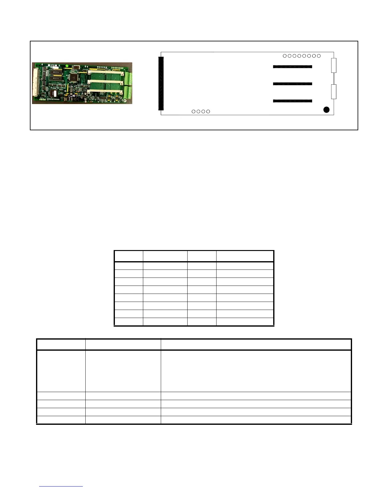
Communication Card
The Communication card enables the PRO-2000 panels to be connected to various communication interfaces such
as RS-232, and RS-422. You must install an RS-232 or RS-422 communication module (or both) into the interface
sockets of the Communication card. It is the installation of the communication modules that defines if the card is
RS-422 and/or RS-232. Field wiring connections on the Communication card are dependent on the installed
module. The RS-422 communication module activates two serial data links on J1. The RS-232 communication
module activates one serial data link on J2.
The communication modules can be inserted in any socket, however, there cannot be two of the same
communication module on each Communication card.
The communication modules are powered through the Communication card. Each communication module uses an
isolated power supply and are fully isolated from the main system and from themselves. There is transient
protection provided on each module and Ground fault detection is separate for each communication module.
RS-422 Signal Name RS-232 Signal Name
J1-1 TX2+ (out) J2-1 TX (out)
J1-2 TX2- (out) J2-2 RX (in)
J1-3 RX2+ (in) J2-3 RTS* (out)
J1-4 RX2- (in) J2-4 CTS* (in)
J1-5 TX1+ (out) J2-5 BRG_out (out)
J1-6 TX1- (out) J2-6 CD* (in)
J1-7 RX1+ (in) J2-7 Not used
J1-8 RX1- (in) J2-8 GND
Table 12: Communication card Pin outs
LED Function Definition
LD1-LD8 (green)
Communication indicators for
the on-board data links
These indicators will blink when data is received or transmitted on one of the
data links.
LD1 (RX1) and LD2 (TX1) for RS-422, S1 (X) side
LD3 (RX2) and LD4 (TX2) for RS-422, S2 (Y) side
LD5 (RX3) and LD6 (TX3) for RS-232
LD7 (RX4) and LD8 (TX4) reserved
LD9 (green) 24V input indicator ON when the 24V power from the Host system is present
LD10 (green) VCC Indicator ON when the local VCC (5 V) regulator is functional
LD11 (green) VISO1 Indicator ON when the local isolated power supply #1 is functional (RS-422, S1)
LD12 (green) VISO2 Indicator ON when the local isolated power supply #2 is functional (RS-232, S3)
Table 13: Communication Card LEDs
J1
Metalized
LD9 LD12
Power Indicators
Connector to
MPU or LCD
Field Wiring
RS-422
Field Wiring
J2
RS-232
LD1 LD8
RS-422 or RS-232 Sockets
Ground
Figure 31: Communication Card Connections