PRO-2000 Installation and Operation Manual
53
The adapter's supervised input # is indicated near the screw connections. The + and - signs on the adapter
indicate the polarity of the connection.
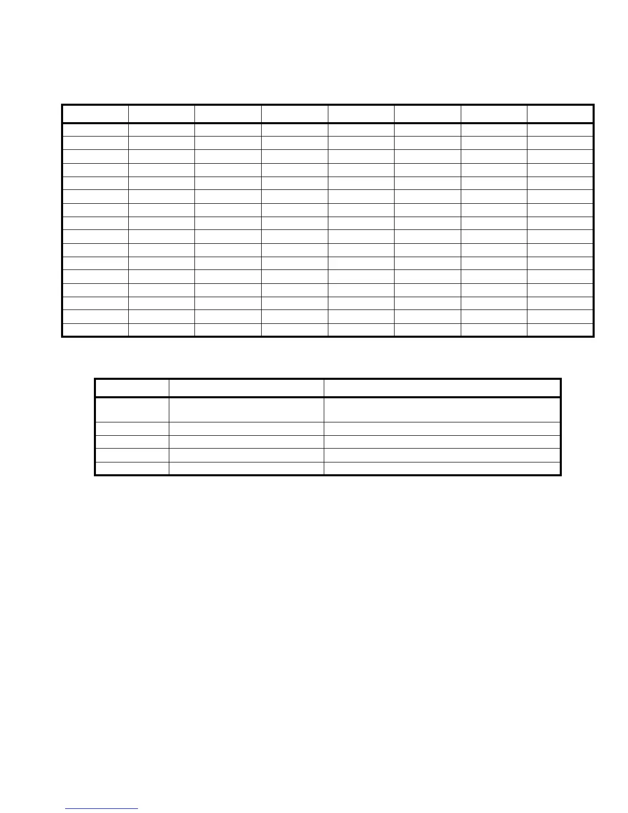
Signal Connection Signal Connection Signal Connection Signal Connection
SI1+ J4-A32 SI9+ J4-A24 SI17+ J4-A16 SI25+ J4-A8
SI1- J4-C32 SI9- J4-C24 SI17- J4-C16 SI25- J4-C8
SI2+ J4-A31 SI10+ J4-A23 SI18+ J4-A15 SI26+ J4-A7
SI2- J4-C31 SI10- J4-C23 SI18- J4-C15 SI26- J4-C7
SI3+ J4-A30 SI11+ J4-A22 SI19+ J4-A14 SI27+ J4-A6
SI3- J4-C30 SI11- J4-C22 SI19- J4-C14 SI27- J4-C6
SI4+ J4-A29 SI12+ J4-A21 SI20+ J4-A13 SI28+ J4-A5
SI4- J4-C29 SI12- J4-C21 SI20- J4-C13 SI28- J4-C5
SI5+ J4-A28 SI13+ J4-A20 SI21+ J4-A12 SI29+ J4-A4
SI5- J4-C28 SI13- J4-C20 SI21- J4-C12 SI29- J4-C4
SI6+ J4-A27 SI14+ J4-A19 SI22+ J4-A11 SI30+ J4-A3
SI6- J4-C27 SI14- J4-C19 SI22- J4-C11 SI30- J4-C3
SI7+ J4-A26 SI15+ J4-A18 SI23+ J4-A10 SI31+ J4-A2
SI7- J4-C26 SI15- J4-C18 SI23- J4-C10 SI31- J4-C2
SI8+ J4-A25 SI16+ J4-A17 SI24+ J4-A9 SI32+ J4-A1
SI8- J4-C25 SI16- J4-C17 SI24- J4-C9 SI32- J4-C1
Table 20: 32 Zone Supervised Input Card Pin outs
LED Function Position
LD1 (green) 24V input indicator
ON when the 24V power from the Host system is
present.
LD2 (green) VCC indicator ON when the local VCC (5V) regulator is functional.
LD3 (green) Isolated 24V power indicator ON when the isolated 24V power supply is activated.
LD4 (green) Isolated +5V power indicator ON when the isolated +5 V power supply is activated.
LD5 (green) Isolated -5V power indicator ON when the isolated -5 V power supply is activated.
Table 21: Supervised Input Card LEDs