MAIN PROCESSING CARDS
64
Control Module
The Control module interfaces standard OUTPUT alarm devices with a PRO-2000 panel via the ADI card. You can
program the module's unique address using two rotary switches located on the front of the mounting bracket. The
module mounts into a 4" square junction box via a mounting bracket (included).
The module can either supervise alarm devices with a supervision circuit or provide a dry Form-C relay contact for
signaling purposes. When used as a supervised output, a secondary voltage source must be provided. Power, from
a UL listed for Fire Protective Signaling Systems (ULC listed in Canada) 24 VDC regulated power source, is used
by the module to switch on the controlled devices. Relay control, with Form-C contacts (unsupervised), is obtained
by breaking off tabs J1 and J2.
The unit can be connected in NFPA Class A or B circuits. The status of the OUTPUT line (normal, open or Short
circuit) latches in the module until polled by the PRO-2000 panel.
A LED indicator flashes each time the module is addressed by a PRO-2000 panel. The module transmits, to the
PRO-2000 panel, the status of the supervised OUTPUT along with the actual analog value of the supervision.
All circuits are power-limited and supervised
Use UL listed (ULC Canada)
Max.Load: 1.5A, 24V DC
indicating devices
Max. current: 2A
connection.
run to provide supervision of
terminals 3 and 4. Break wire
Do not use looped wire on
hour battery back-up.
24VDC power supply with 24
in Canada) regulated, isolated
Use only "UL listed” (ULC listed
(TWISTED PAIR, SHIELDED)
EOL Resistor is supplied with the Control Module
CONTROL MODULE
(-)
*
56
NOTE 2
NOTE 3
NOTE 1
SUPPLY
POWER
24VDC
(+)
4
-
+
(-)(+)(+)
87
9
(+)
2
(-)
3
(-)
1
3.
2.
NOTES:
1.
To ADI Card
LPX-
LPX+
LPY-
LPY+
N.O. CONTACTS)
1/4W, 5%
47K OHMS
EOL RES.
(24VDC COIL
EOL RELAY
UL LISTED
*
MODULE/DETECTOR
TO NEXT
MODULE/DETECTOR
FROM LAST
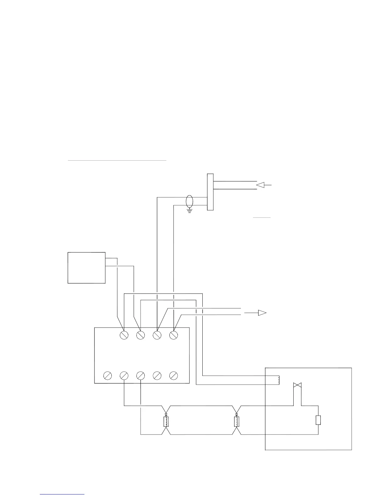
Figure 49: Class B Indicating Circuit Wiring of Control Module