PRO-2000 Installation and Operation Manual
59
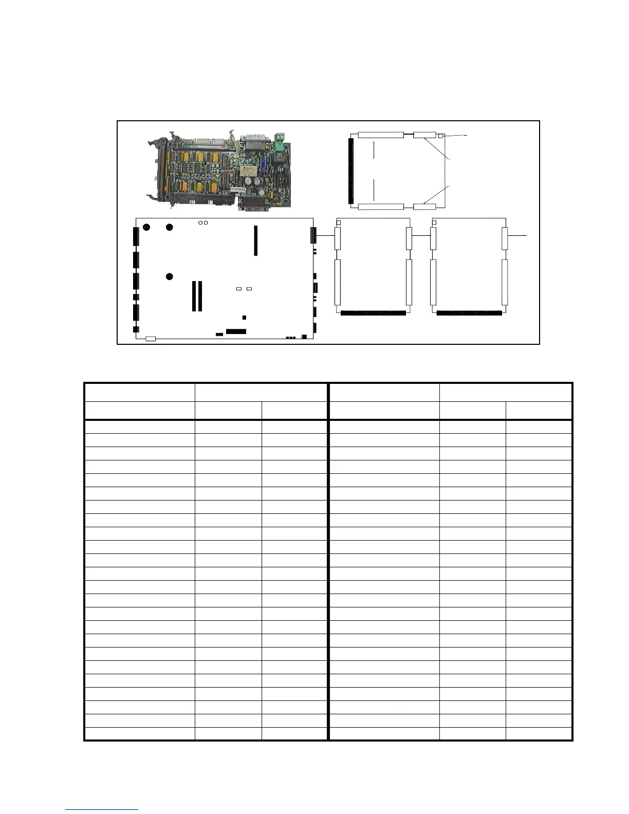
MIMIC Driver Module
The MIMIC Driver Module drives the LEDs on the MIMIC displays for the X0M, X2M, and X6M panels. The LCD
card controls the MIMIC Driver module. Each MIMIC Driver module supports up to 48 LEDs and 24 push buttons
via two connectors. Flat ribbon cables with crimping capabilities are used to attach LEDs on a MIMIC display. A
total of 3 MIMIC Modules can be cascaded from a single LCD card.
LEDs 1-24 J5 LEDs 25-48 J2
LED Number Anode Cathode LED Number Anode Cathode
1122512
2342634
3562756
4782878
5 9 10 29 9 10
61112301112
7 1314311314
8 1516321516
9 1718331718
10 19 20 34 19 20
11 21 22 35 21 22
12 23 24 36 23 24
13 25 26 37 25 26
14 27 28 38 27 28
15 29 30 39 29 30
16 31 32 40 31 32
17 33 34 41 33 34
18 35 36 42 35 36
19 37 38 43 37 38
20 39 40 44 39 40
21 41 42 45 41 42
22 43 44 46 43 44
23 45 46 47 45 46
24 47 48 48 47 48
Table 25: MIMIC Driver Module LEDs
J2
J4
J5
J6
J8
J9
J7
J17
J11J10
J12
SW1
SW2
1
MIMIC DRIVER
LCD CARD
MIMIC DRIVER
Connector to
switches or
pushbuttons
(Reserved for
future use)
Flat ribbon cable
Crimped connections
for 48 LED's
J6
J5 J4
J1J2
Input connector from LCD
(or previous mimic driver)
External
power
Output connection
to cascade to
another mimic driver
module
Figure 45: MIMIC Driver Module and Connections