MAIN PROCESSING CARDS
42
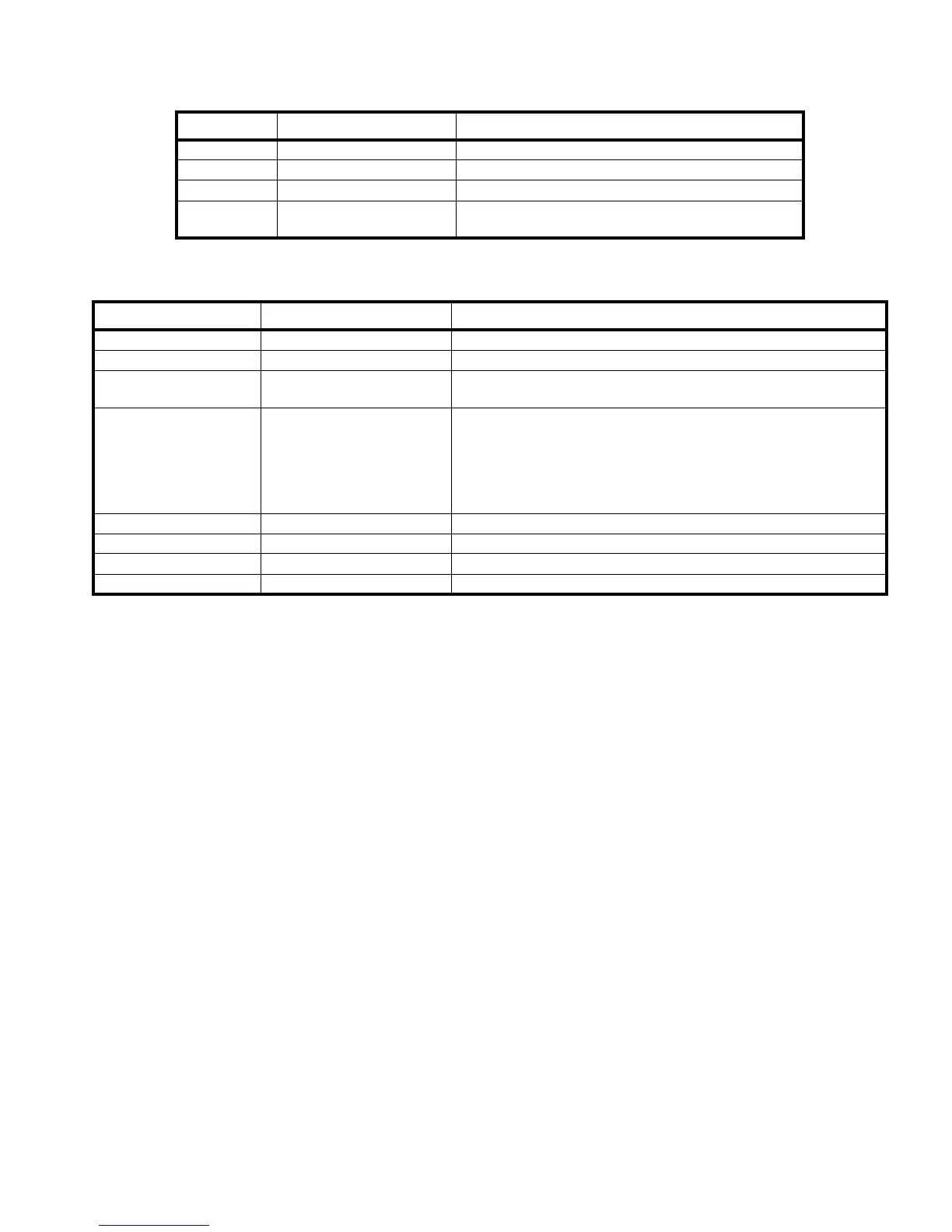
Jumper Function Position
JP5 Watchdog enable Installed
JP4 Watchdog one-shot mode Installed
JP6 Lithium Battery enable Installed on site
JP2, JP3 RAM size function
- Non installed when 128 K x 8 RAM chips are used.
- Installed when 512 K x 8 RAM chips are used.
Table 10: LCD Jumpers
LED Function Definition
LD39 (green) Status indicator Reserved
LD34 (green) Running indicator Blinks when the LCD is executing its normal program
LD40 - LD42
LD46 - LD50 (red)
Error code indicators Used to report internal error conditions
LD51 - LD58 (green)
Communication indicators for
the on-board data links
These indicator will blink when data is received or transmitted on one
of the data links.
LD51 (RX1) and LD52 (TX1) for RS-422, S1 (X) side
LD53 (RX2) and LD54 (TX2) for RS-422, S2 (Y) side
LD55 (RX3) and LD56 (TX3) for RS-232
LD57 (RX4) and LD58 (TX4) Reserved
LD28 (green) 24V input indicator ON when the 24V input connectors J6, J7, J8, or J9 are powered
LD1 (green) VISO1 indicator ON when the local isolated power supply #1 is functional (RS-422)
LD2 (green) VISO2 indicator ON when the local isolated power supply #2 is functional (RS-232)
LD27 (green) Mimic Power indicator ON when power is available on the mimic connector, J2
Table 11: LCD LEDs