LCD
TX1+
4
1
2
3
J6
X2 PANEL
5
6
TX1-
28V
GND
RX1+
RX1-
RX2-
RX2+
GND
28V
TX2-
TX2+
6
2
5
4
3
J8
1
GND
28V
6
J9
5
RX2-
RX2+
TX2-
TX2+
28V
GND
RX1-
LCD
X0 PANEL (REPEATER)
RX1+
GND
28V
TX1-
TX1+
6
2
5
4
3
J8
1
6
2
5
4
3
J6
1
TX1+
28V
TX1-
GND
RX1-
RX1+
X0 PANEL (REPEATER)
TX2+
28V
TX2-
GND
RX2+
RX2-6
5
4
J8
3
2
1
6
5
4
J6
2
3
1
LCD
Omit these wires
for stub operation
Note 2
Note 1
RX1- 6
X6 PANEL
28V
RX1+
GND
TX1+
TX1-
RX2-
RX2+
28V
GND
TX2-
MPU
TX2+
3
4
5
1
J2
2
6
5
2
4
3
1
J3
3
4
5
2
6
3
4
5
6
1
J8
RX1+
RX1-
GND
TX1+
TX1-
28V
RX2-
RX2+
GND
28V
2
X0 PANEL (REPEATER)
1
J6
TX2+
TX2-
LCD
Wires to be omitted
for stub operation
RX2- 6
RX2+
RX1-
RX1+
28V
GND
TX2-
TX2+
TX1-
28V
GND
3
4
5
J8
1
2
6
5
2
4
3
TX1+
LOCAL LCD
J6
1
Note 3
Note 2
Note 1
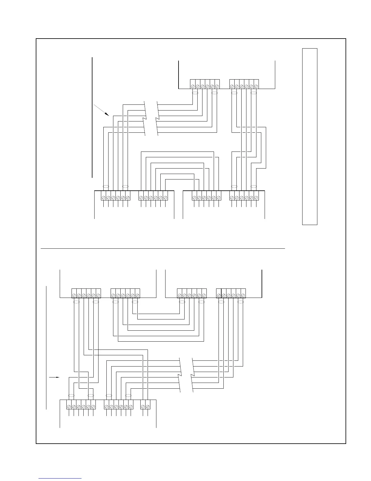
ALL CIRCUITS ARE POWER-LIMITTED AND SUPERVISED
ALL CIRCUITS ARE POWER-LIMITED AND SUPERVISED
X2 SERIES Max. 28 V supply cable length depends on configuration.
Must run in conduit separate from Tx and Rx cables.
Maximum current (short circuit: 4.5 Amp).
Maximum current (short circuit: 1 Amp).
X6 SERIES Max. 28 V supply cable length depends on configuration.
Must run in conduit separate from Tx and Rx cables.
NOTES
1.
Number of Repeaters limited by the configuration of the Host panel.
An external power supply can be used to extend the number of Repeaters.
Use only UL Listed for Fire Protective Signaling Systems (ULC Listed in Canada)
regulated, isolated 24VDC power supply (supervised and power limited).
3.
Use shielded, twisted pair cables, one pair for Tx lines, one pair for Rx lines.
No branches
or T-Taps allowed. Shields to be connected according to specific
system Wiring Diagrams.
Maximum cable length for communication: 1 Km between panels.
Maximum cable resistance (per pair): 40 Ohms.
Maximum loop current (short circuit): 150 mA.
2.
Figure 24: X2 and X6 Network Wiring to a Repeater, X0
Minimum detected ground fault impedance is 10K ohms.