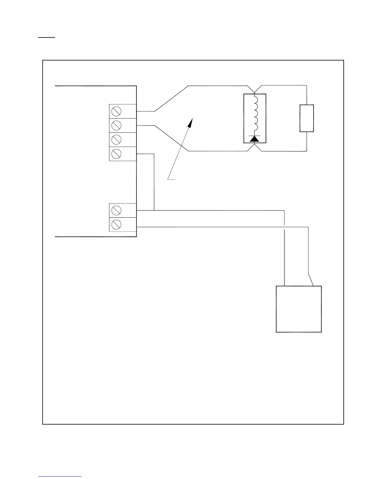
1. MORE THAN ONE RELAY, VALVE OR SOLENOID PER OUTPUT IS NOT ALLOWED.
EOL
24VDC
POWER
SUPPLY
(+) (-)
POWER LIMITED, SUPERVISED CIRCUITS
Jumper to be installed as per
supervision jumper Table 22.
See Appendix B for compatible NAC
or releasing devices.
1.
3.
NOTES:
(+)
(-)
SO CARD
2
1
1
4
2
J2
Note 3
J4
VIN+
VIN-
Note 4
2.
Max. allowable circuit voltage: 28 VDC
Max. current load (per relay circuit): 2A
4.
3
GND
C
NC
NO
ALL CIRCUITS ARE POWER-LIMITED
AND SUPERVISED
(NOTE 2)
Use only UL listed for Fire Protective Signaling Sys-
tems (ULC Listed in Canada) regulated, isolated
24VDC power supply (supervised and power-limited).
Use MP-300SP when NAC circuit
EOL devices must be on a mounting
plate. Use MP-320SP when solenoid
circuit EOL devices must be on a
mounting plate.
5. Minimum detected ground fault impedance is 10K ohms.