Note 1
Note 10
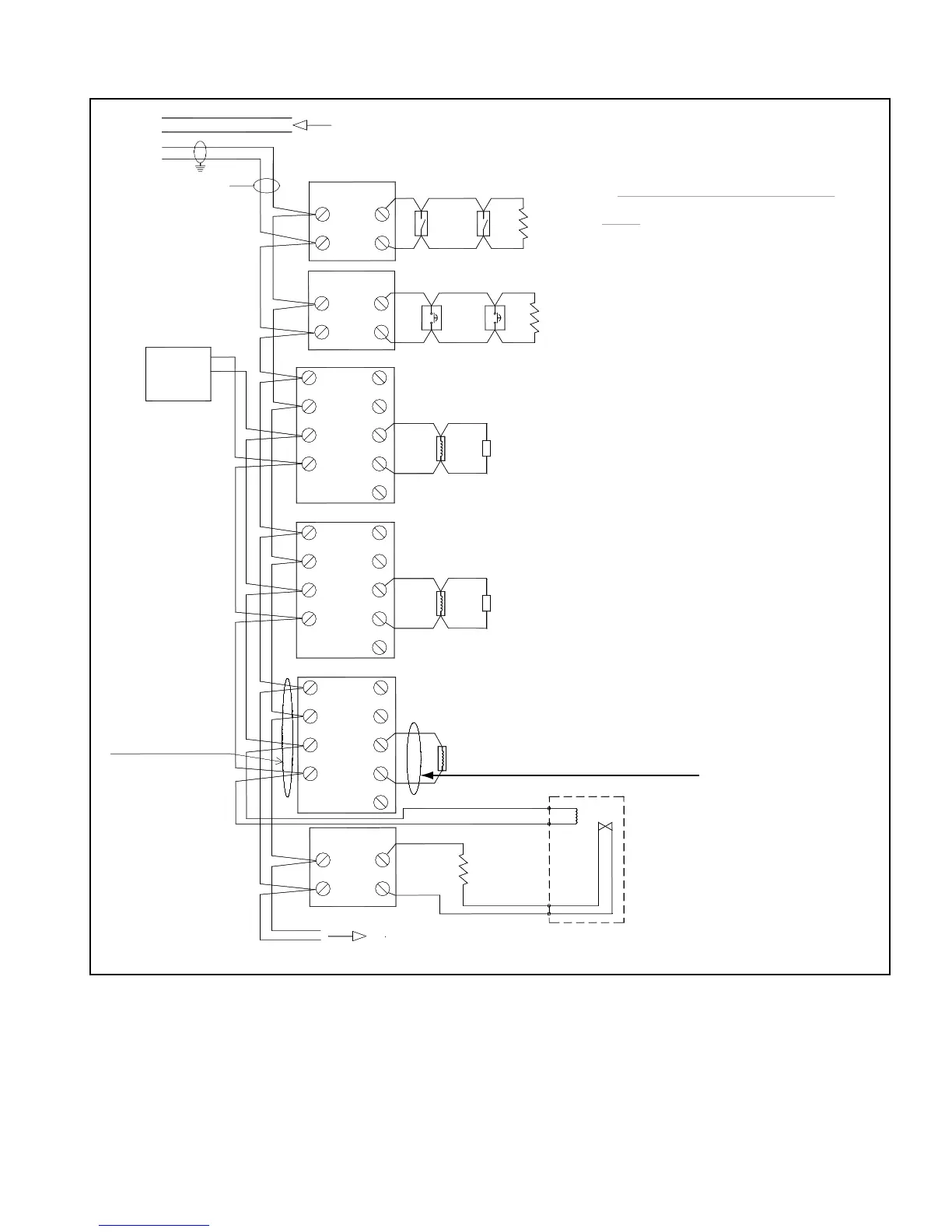
47K EOLR
FROM LAST MODULE/DETECTOR (Loop configuration optional)
Use only cables type
PLF, PLFA, PLFP+PLFR
SUPPLY
NOTE 4
NOTE 5
POWER
24VDC
+
-
TO NEXT MODULE/DETECTOR
Note 9
MODULE
Note 6,8
Note 3
Note 6,7,11
Note 2
POWER-LIMITED CIRCUITS
(loop mode)
To ADI card
connections
addressable
loop
LPX+
LPX-
LPY-
LPY+
MONITOR
CIRCUIT SUPERVISED AND POWER-LIMITED
EOL Resistor is supplied with the Monitor Module.
Manual release switch
Abort switch (self restoring switch)
UL listed only (ULC Canada).
For NAC circuits use UL Listed for Fire Protective Signaling
Systems (ULC Listed in Canada) regulated, isolated 24VDC
power supply (supervised and power limited).
Do not use looped wire on
terminals 3 and 4. Break wire
run to provide supervision of
Use UL listed (ULC Canada)
Max.Load: 1.5A, 24VDC
Use UL listed (ULC Canada)
Max.Load: 1.5A, 24VDC
Release Device (Valve, Solenoid)
Max.Load: 1.5A, 24VDC
Min.Load: 0.005A, 24VDC
Use UL listed (ULC Canada)
UL listed (ULC Canada) EOL relay
N.O. contacts
Classe B, style 1 (NFPA 72-35) circuit
Non power-limited circuit
47K OHMS
1/4W, 5%
Note 1
Note 1
Note 1
47K EOLR
47K EOLR
General Alarm
NAC devices
Release
NAC devices
(24VDC COIL)
10.
11.
8.
9.
7.
NOTES:
UL listed only (ULC Canada).
connection.
NAC devices
6.
5.
2.
4.
3.
1.
5
7
6
(-)
(+)
8
(+)
(-)
9
(-)
(+)
(-)
(+)
3
4
2
1
(+)
(-) (+)
(-)
1
2
7
6
MODULE
CONTROL
MODULE
2
1
(-)
(+)
7
(+)
6
(-)
MONITOR
4
3
(+)
(-)
(+)
(-)
CONTROL
MODULE
7
(+)
(-)
5
6
(-)
(+)
1
2
9
8
MODULE
CONTROL
(-)
(+)
(-)
(+)
3
4
(+)
(-)
(+)
2
5
6
7
8
(-)
19
MODULE
2
1
(-)
(+)
7
(+)
6
(-)
MONITOR
M500M
EOLR
47K OHMS
1/4W, 5%
Note 1
EOLR
If multiple zones are configured in a system,
each one should have its own power supply
and style 7 wiring should be used for the SLC.
Isolation should be provided between the zones
as per Figure 50.
For Releasing circuits use Special Application Mircom
APS-14127-00 Auxiliary Power Supply.