PRO-2000 Installation and Operation Manual
37
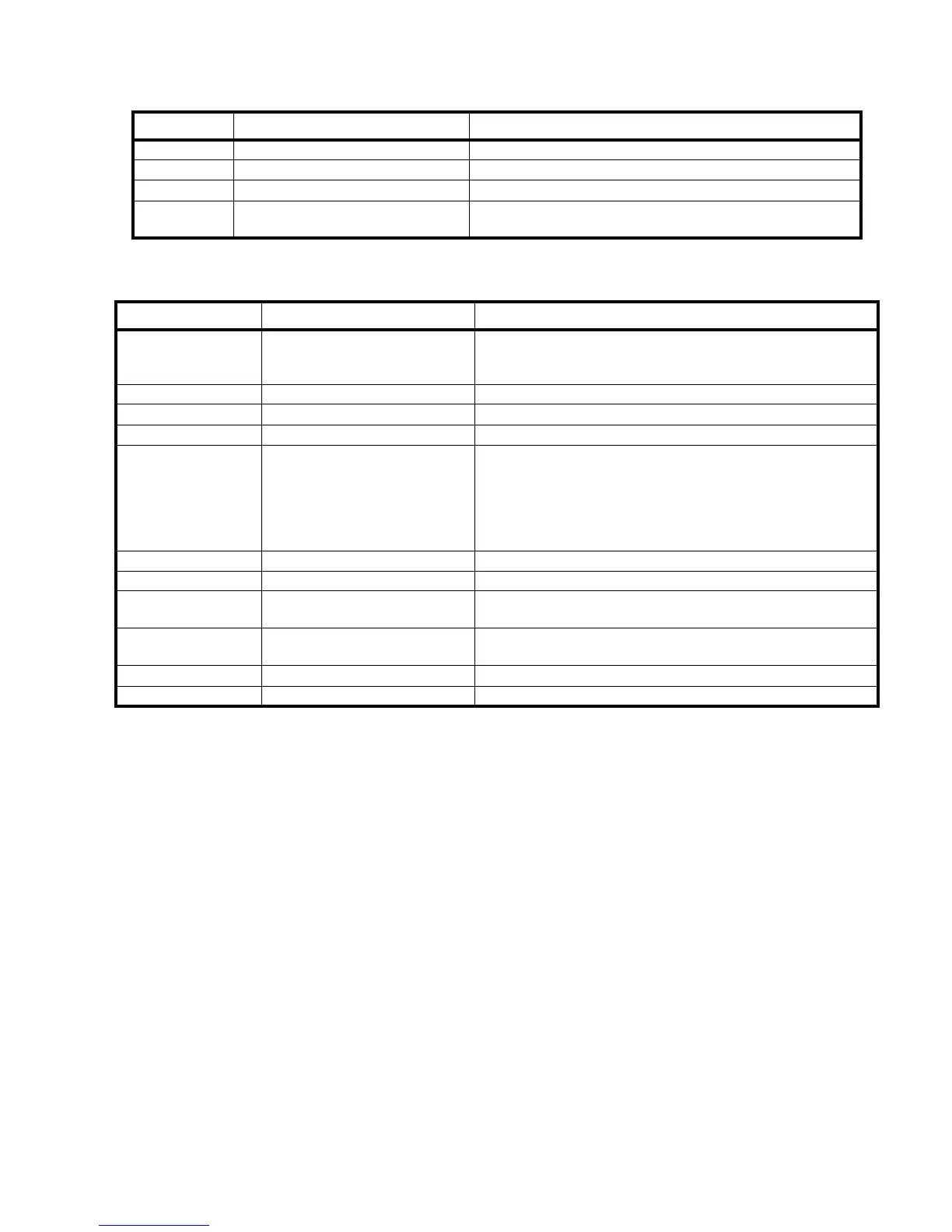
Jumper Function Position
JP2 Watchdog Enable Installed
JP1 Watchdog one-shot mode Installed
JP3 Lithium Battery Enable Installed on site
JP4 RAM Size Selection
Non installed when 128K x 8 RAM chips are used.
Installed when 512K X 8 RAM chips are used.
Table 5: MPU Jumpers
LED Function Definition
LD1 (red) Reset indicator
ON when the MPU is in a hardware reset state
- At power up, or
- On a fatal hardware or software failure
LD2 (green) Status indicator Not used (reserved)
LD3 (green) Running indicator Blinks when the MPU is executing its normal program
LD4-LD11 (red) Error code indicators Used to report internal error conditions
LD12-LD19
Communication indicators for the
on board data links
These indicators will blink when data is received or transmitted
on one of the data links.
LD12 (RX1) and LD13 (TX1) for RS-422, X side (local LCD)
LD14 (RX2) and LD15 (TX2) for RS-422, Y side
LD16 (RX3) and LD17 (TX3) for RS-232
LD18 (RX4) and LD19 (TX4): are reserved
LD20 (green) 24 V input indicator ON when the 24V input connector J10 is powered.
LD21 green) VCC indicator ON when the local VCC (5V) regulator is functional
LD22 green) VISO1 indicator
ON when the local isolated power supply #1 is functional (RS-
422 power supply)
LD23 (green) VISO2 indicator
ON when the local isolated power supply #2 is functional (RS-
232 power supply)
LD24 (green) LCD loop power, X side ON when power is available on the LCD connector, X side, J2
LD25 (green) LCD loop power, Y side ON when power is available on the LCD connector, Y side, J3
Table 6: MPU LEDs