MAIN PROCESSING CARDS
50
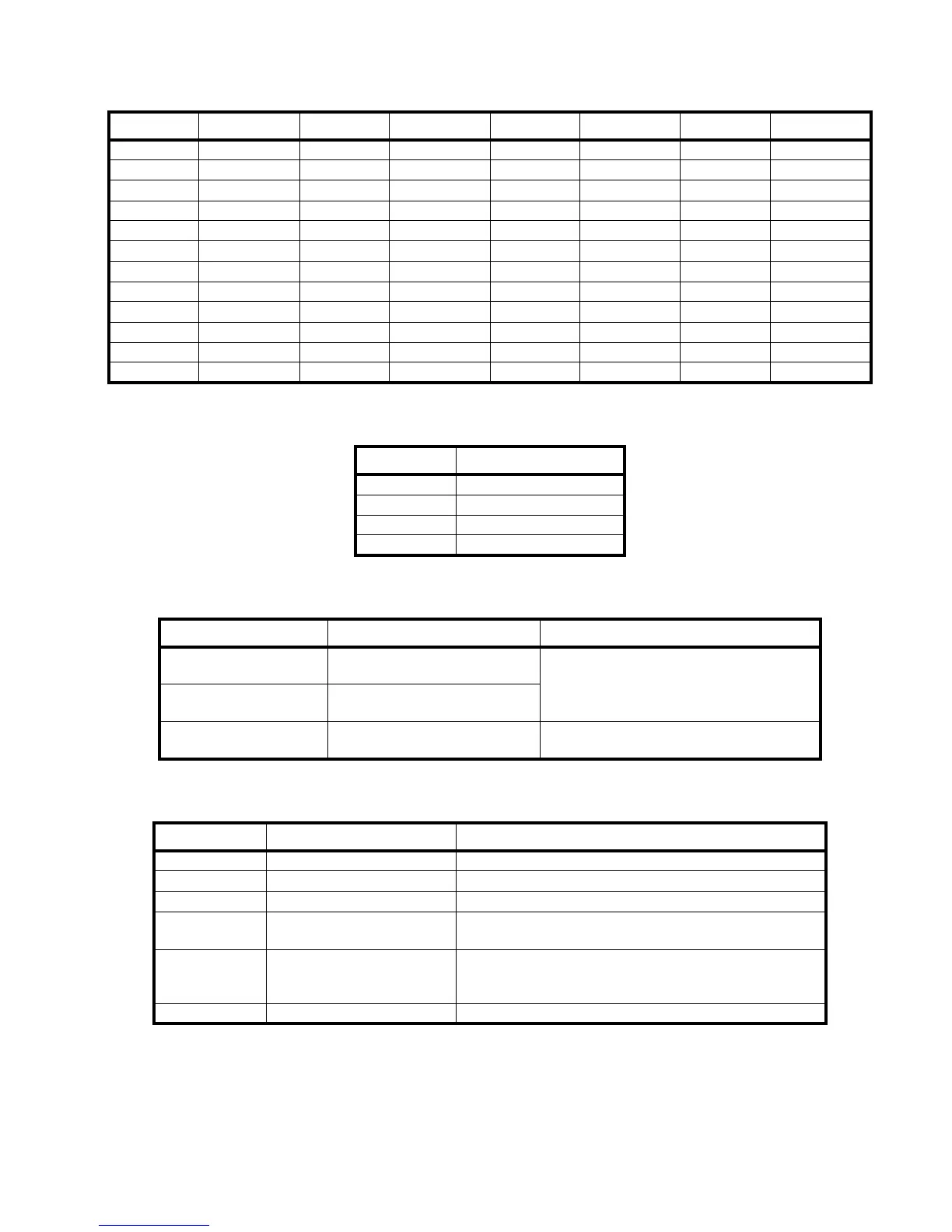
Signal Connection Signal Connection Signal Connection Signal Connection
SO1-NO J5-1 SO4-NO J5-13 SO7-NO J5-25 SO10-NO J5-37
SO1-NC J5-2 SO4-NC J5-14 SO7-NC J5-26 SO10-NC J5-38
SO1-COM J5-3 SO4-COM J5-15 SO7-COM J5-27 SO10-COM J5-39
GND J5-4 GND J5-16 GND J5-28 GND J5-40
SO2-NO J5-5 SO5-NO J5-17 SO8-NO J5-29 SO11-NO J5-41
SO2-NC J5-6 SO5-NC J5-18 SO8-NC J5-30 SO11-NC J5-42
SO2-COM J5-7 SO5-COM J5-19 SO8-COM J5-31 SO11-COM J5-43
GND J5-8 GND J5-20 GND J5-32 GND J5-44
SO3-NO J5-9 SO6-NO J5-21 SO9-NO J5-33 SO12-NO J5-45
SO3-NC J5-10 SO6-NC J5-22 SO9-NC J5-34 SO12-NC J5-46
SO3-COM J5-11 SO6-COM J5-23 SO9-COM J5-35 SO12-COM J5-47
GND J5-12 GND J5-24 GND J5-36 GND J5-48
Table 15: 12 Zone Supervised OUTPUT Card Pin outs - DSUB Termination
Signal Connection
VIN+ J4-1
VIN- J4-2
Vout+ J4-3, J5-49, J5-50
Vout- J4-4
Table 16: External Power Supply Connections
Jumper Function Position
JP2
Supervision mode for OUTPUT
#1
Installed for la supervision (Use EOL
jumper for UL release device. Refer to
Release Service Devices section). Not
installed for dry contact.
JP4, 6, 8, 12, 14, 16, 18,
20, 22, 24
Supervision mode for outputs 2,
3, 4, 5, 6, 7, 8, 9, 10, 11, 12
JP3, 5, 7, 9, 11, 13, 15,
17, 19, 21, 23, 25
Reserved Not installed
Table 17: 12 Zone Supervised OUTPUT Card Jumpers
LED Function Position
LD3 (green) 24V input indicator ON when the 24V power from the Host system is present.
LD2 (green) Fused 24V input indicator ON when the fused 24V from the Host system is present.
LD1 (green) VCC indicator ON when the local VCC (5V) regulator is functional.
LD5 (green)
External power input
indicator
ON when a 24V power supply is connected to the external
power input (J4-1, J4-2)
LD4 (green)
External power OUTPUT
indicator
ON when 24V power is available on the external power
connector (J4-3, J4-4). Indicates that the power is
available for the supervision circuits.
LD6-17 (green) outputs #1 through #12 State ON when corresponding OUTPUT is activated.
Table 18: 12 Zone Supervised OUTPUT Card LEDs