PRO-2000 Installation and Operation Manual
41
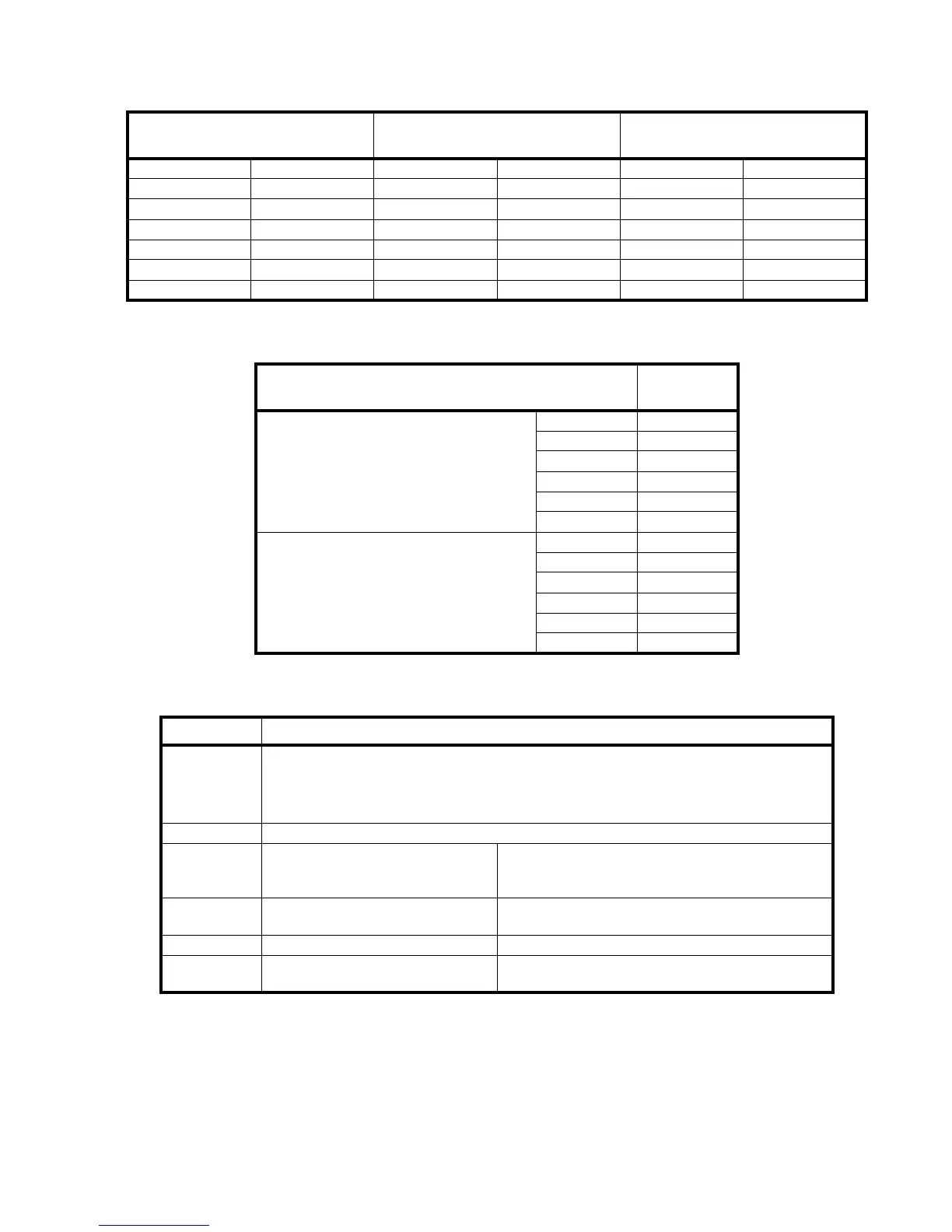
COMM Loop (S1 (J6) X) COMM Loop (S2 (J8) Y)
RS-232 Modular Phone Jack
(J19)
Signal Pin Signal Pin Signal Pin
TX1+ (out) 1 TX2+ (out) 1 TX (out) 5
TX1- (out) 2 TX2- (out) 2 RX (in) 2
24V 3 24V 3 RTS* (out) 3
GND4GND4CTS* (in)6
RX1+ (in) 5 RX2+ (in) 5 CD* (in) 1
RX1- (in) 6 RX2- (in) 6 GND 4
Table 7: LCD Pinouts
Common Alarm and Trouble Relays (J4)
2A max@30V DC Resistive
Pin
Trouble
C1 1
NC1 2
NO1 3
C2 4
NC2 5
NO2 6
Alarm
C1 7
NC1 8
NO1 9
C2 10
NC2 11
NO2 12
Table 8: LCD Relays
Switch Position and description
SW1
For X2- 0: Printer, 1: configuration, 2: Normal/Diagnose; 3: ModBus, 4: LCD, 5: Network,
6: Redundant, E: Firmware, F: Default Config
For X0-: with SW2 bit 6 ON, RS422 Baudrate selection: 4: 2400, 5: 4800, 6: 9600,
7: 19200, 9: 64000.
SW3 Used to reset LCD card
SW2 4 (MSB), 3, 2, 1 (LSB)
Address ID of the LCD.
When OFF (Address ID = 0), X2 mode is selected.
Otherwise (Address ID 1-15), X0 mode is selected.
SW2 5
X0, with power supply.
ON returns hardware trouble to master.
SW2 6 RS-422 Baud Rate - ON= see SW1, OFF = 19200.
SW2 7 (MSB) and 8 (LSB)
Indicates the number of LCD Expander or Mimic
Driver module connected to the LCD.
Table 9: LCD Switches