MAIN PROCESSING CARDS
56
See Appendix B for the List of Addressable Devices which are compatible with Addressable Device Interface.
NOTE:
1. MORE THAN ONE RELAY, VALVE OR SOLENOID PER OUTPUT IS NOT ALLOWED.
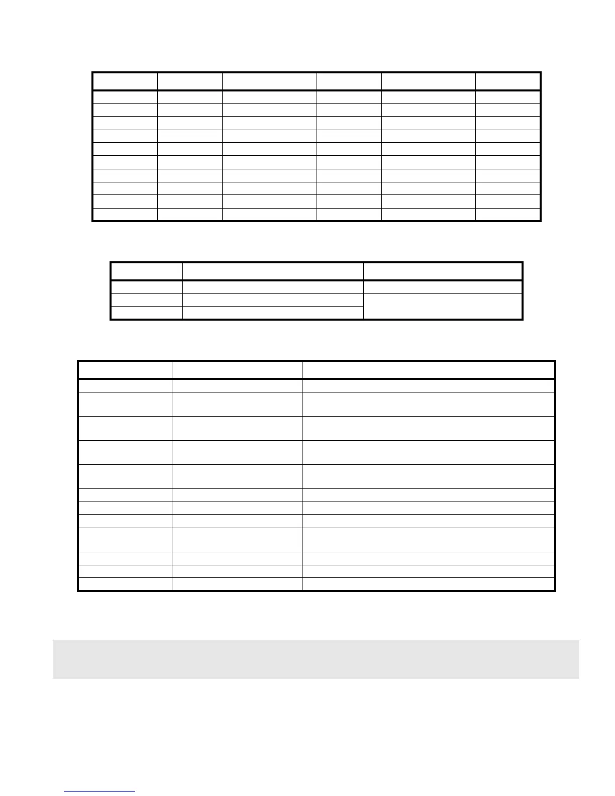
Signal Connection Signal Connection Signal Connection
NO1 J7-1 NC4 J7-11 LPY+ (loop2) S4 J6-1
NC1 J7-2 COM4 J7-12 LPY- (loop2) S4 J6-2
COM1 J7-3 VIN+ J7-13 LPX+ (loop2) S3 J6-3
NO2 J7-4 VIN- J7-14 LPX- (loop2) S3 J6-4
NC2 J7-5 Vout+ J7-15
COM2 J7-6 Vout- J7-16
NO3 J7-7 LPY+ (loop1) S2 J7-17
NC3 J7-8 LPY- (loop1) S2 J7-18
COM3 J7-9 LPX+ (loop1) S1 J7-19
NO4 J7-10 LPY- (loop1) S1 J7-20
Table 22: ADI Card Pin outs
Jumper Function Position
JP1 and JP2 Reserved Installed
JP3 Supervision mode for OUTPUT #1
Installed for la supervision
Not installed for dry contacts
JP4, JP5, JP6 Supervision mode for outputs 2, 3, 4
Table 23: ADI Card Jumpers
LED Function Position
LD1 (green) Running indicator Blinks when the ADI is executing its normal program
LD2 (green) X1 Stub polling indicator
Will be ON when the ADI card is polling a device on Stub X1
(J7-19, J7-20) S1
LD3 (green) Y1 Stub polling indicator
Will be ON when the ADI card is polling a device on Stub Y1
(J7-17, J7-18) S2
LD4 (green) X2 Stub polling indicator
Will be ON when the ADI card is polling a device on Stub X2
(J6-3 J6-4) S3
LD5 (green) Y2 Stub polling indicator
Will be ON when the ADI card is polling a device on Stub Y2
(J6-1, J6-2) S4
LD6 - LD9 (red) Line break indicator ON if a break on stub X1(LD6), Y2 (LD7), X2(LD8), Y2(LD9)
LD10 - LD17 (green) Internal status codes Used to report internal status
LD18 (green) 24V input indicator ON when the 24V power from the Host system is present
LD19 (green) Fused 24V input indicator
ON when the fused24V power from the Host system is
present
LD21 (green) VCC indicator ON when the local VCC (5V) regulator is functional
LD20 (green) Isolated 24V power indicator ON when the isolated 24V power supply is activated
LD22 (green) Isolated 5V power indicator ON when the isolated 5V power supply is activated
Table 24: ADI Card LEDs