PRO-2000 Installation and Operation Manual
71
OPERATING INSTRUCTIONS
The LCD Panel
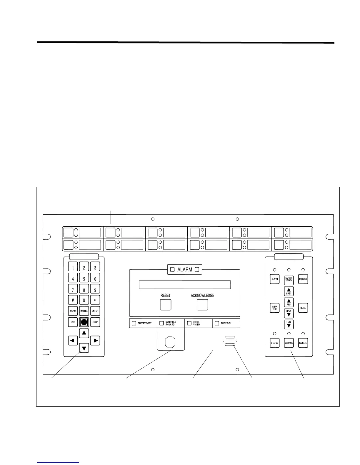
The LCD Panel provides the main user interface for the PRO-2000 Series. The front panel divides into four
functional areas:
SYSTEM STATUS Alarm indicators (also called Dual Alarm indicators), the Liquid Crystal Display, the Reset and
Acknowledge push buttons, the Supervisory, Controls Enabled, Panel Failed, Power indicators
and the Control Key Switch.
DISPLAY Provides visual indication of, and access to, the system status. The DISPLAY area contains the
Alarm, Supervisory, Trouble, Status, Service, Isolate, and Lamp Test push buttons and
associated indicators. There are also directorial buttons to scroll through Event Lists on the LCD.
The More push button provides additional details on the currently displayed event condition in the
LCD.
USER-DEFINED Provides user control of Special Functions through configurable push buttons (12) and LEDs (24).
SYSTEM Provides access to the system's Menu selection to control certain data and functions such as Event
Log, Access Level, Set Clock, Panel Brightness, and Maintenance Mode settings. This area is
security access protected.
DISPLAY
USER DEFINED SECTION
LCD DISPLAY - USER DEFINED MESSAGES
SYSTEM KEY PAD
CONTROL KEY SWITCH
USER CONTROL SECTION
DISPLAY KEY PADBUZZER
Figure 55: LCD Panel