PRO-2000 Installation and Operation Manual
55
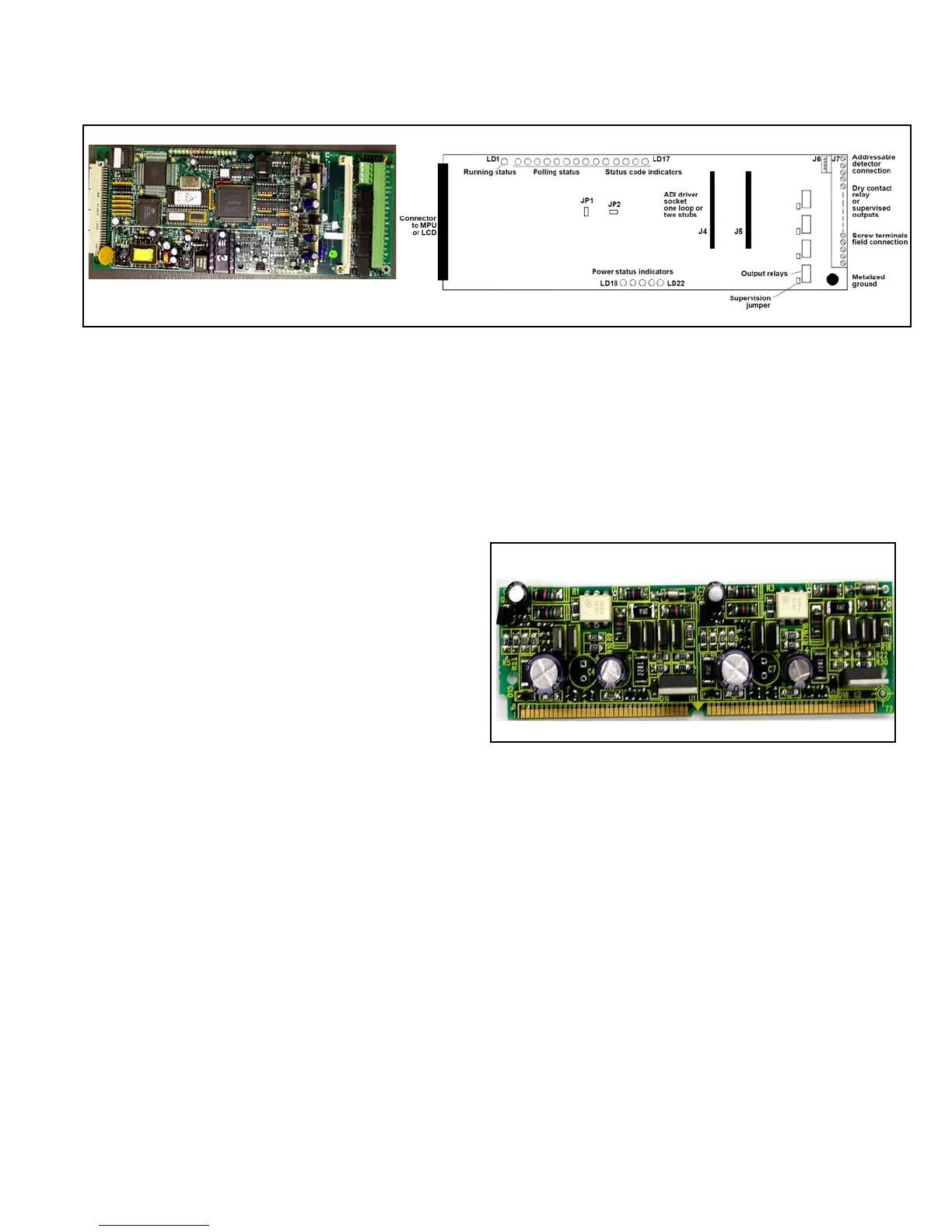
ADI - Addressable Device Interface card
The ADI card supports up to two loops (complying with the operation and supervision requirements of NFPA
Signalling Line Circuit Style 6) of detectors or up to four stubs (complying with NFPA SLC Style 4 requirements).
You can have up to 99 detectors and 99 modules on each loop or stub for a total monitoring capacity of 600
devices - limited by memory. The ADI card interfaces with addressable sensors (photoelectric, ionization and
thermal), addressable modules (monitor and control) and Conventional Detector Interface (CDI) modules.
The ADI's modular design provides two sockets (J4 and J5) for the ADI Drivers. Each ADI Driver can support one
loop or two stubs (J4 for Loop 1 and J5 for Loop 2).
To install an ADI Driver on the ADI card, proceed as follows:
1. Press the ADI Driver module into the ADI card
socket
2. Rotate it down until the side tabs click securing the
ADI Driver in place.
To remove an ADI Driver from the ADI card,
proceed as follows:
1. Gently pull out two side tabs holding the card in
place.
2. Pull the ADI Driver module out of the ADI card
socket.
The metallic-mounting hole on the ADI card is used for transient protection and for Ground fault detection making
a connection between the card and the chassis.
In addition to the addressable detector interface, this card provides four relay outputs, which can be configured as
supervised or unsupervised outputs.
To use dry contacts, no external power is required. The supervision jumper should be removed. To activate
supervision circuits of the ADI card, an external power supply must be connected to the J7 Pin 13 (VIN +) and 14
(VIN -). To configure each individual OUTPUT as supervised, insert the supervision jumper for that output.
Figure 42: ADI Driver Module
Figure 41: ADI - Addressable Device Interface Card and Connections