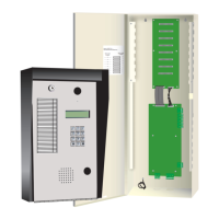
PRO-2000 Installation and Operation Manual
iv
List of Tables
Table 1: Table of features .................................................................................................................... 3
Table 2: MPU Pinouts .......................................................................................................................... 36
Table 3: MPU Relays ........................................................................................................................... 36
Table 4: MPU Switches ........................................................................................................................ 36
Table 5: MPU Jumpers ......................................................................................................................... 37
Table 6: MPU LEDs .............................................................................................................................. 37
Table 7: LCD Pinouts ........................................................................................................................... 41
Table 8: LCD Relays ............................................................................................................................ 41
Table 9: LCD Switches ......................................................................................................................... 41
Table 10: LCD Jumpers ........................................................................................................................ 42
Table 11: LCD LEDs ............................................................................................................................. 42
Table 12: Communication card Pin outs ............................................................................................... 44
Table 13: Communication Card LEDs.................................................................................................... 44
Table 14: 12 Zone Supervised OUTPUT Card Pin outs - Screw Termination ....................................... 49
Table 15: 12 Zone Supervised OUTPUT Card Pin outs - DSUB Termination ....................................... 50
Table 16: External Power Supply Connections ..................................................................................... 50
Table 17: 12 Zone Supervised OUTPUT Card Jumpers ....................................................................... 50
Table 18: 12 Zone Supervised OUTPUT Card LEDs ............................................................................ 50
Table 19: 24 Zone Supervised Input Card Pin outs .............................................................................. 52
Table 20: 32 Zone Supervised Input Card Pin outs .............................................................................. 53
Table 21: Supervised Input Card LEDs ................................................................................................. 53
Table 22: ADI Card Pin outs .................................................................................................................. 56
Table 23: ADI Card Jumpers ................................................................................................................. 56
Table 24: ADI Card LEDs ...................................................................................................................... 56
Table 25: MIMIC Driver Module LEDs ................................................................................................... 59
Table 26: MIMIC Driver Module LEDs.................................................................................................... 60
Table 27: LCD Expander LEDs.............................................................................................................. 60
Table 28: System Status ....................................................................................................................... 72
Table 29: Indicators and Push buttons from Display Panel ................................................................... 73
Table 30: PRO-2000 - Device ID ........................................................................................................... 76
Table 31: MIMIC Driver Module LEDs ................................................................................................... 86
Table 32a: Device Trouble .................................................................................................................... 88
Table 32b: Device Trouble (continuation) ............................................................................................. 89
Table 33a: Card Trouble ....................................................................................................................... 90
Table 33b: Card Trouble (continuation) ................................................................................................. 91
Table 33c: Card Trouble (continuation) ................................................................................................. 92
Table 34: Battery Capacity - Panel Specific Configuration .................................................................... 93
Table 35: X2 Panel Standby Current Consumption - Main Power Supply ............................................ 94
Table 36: X2 Panel Standby Current Consumption - Battery back-up .................................................. 95
Table 37: X2 Panel Alarm Current Consumption - Battery back-up ...................................................... 96
Table 38: X6 Panel Standby Current Consumption - Main Power Supply ............................................ 97
Table 39: X6 Panel Standby Current Consumption - Battery back-up .................................................. 98
Table 40: X6 Panel Alarm Current Consumption - Battery back-up ...................................................... 99
Table 41: System Components Current Consumption - External Power Supply .................................. 100
 Loading...


