6.3 Mounting Position
6 - 5
1
OVERVIEW
2
SYSTEM
CONFIGURATION
3
SPECIFICATIONS
4
PART NAME AND
SETTINGS
5
EMC AND LOW
VOLTAGE
DIRECTIVE
6
INSTALLATION
7
WIRING
8
OPTION
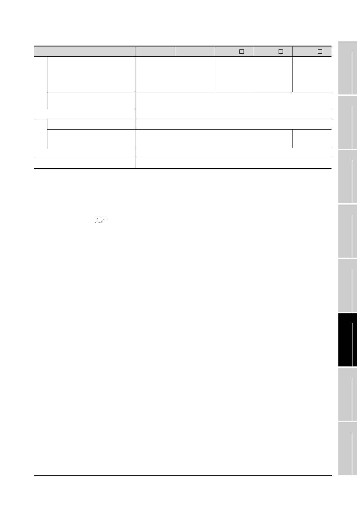
Unit: mm (inch)
*1 This value differs depending on the cable used.
Please contact your local Mitsubishi Electric System & Service Co., Ltd.
The value indicated in the table is a reference value.
*2 This value is for use of the coaxial cable 3C-2V (JIS C 3501).
For specifications of the cable, refer to the following manual.
MODEL GT15V-75V4R1 Video/RGB Input Unit MODEL GT15V-75V4 Video Input Unit MODEL GT15V-
75R1 RGB Input Unit User's Manual (Section 2.4.1 Specifications of the cables (coaxial cables) used when
displaying video images)
*3 This value differs depending on the cable used.
If the bending radius of the cable used is greater than the value specified above, apply the value of the cable
used.
Type GT1595 GT1585
GT157 GT156 GT155
A
External I/O unit
50(1.97) or more
[20(0.79) or more]
50(1.97)
or more
[24(0.94)
or more]
50(1.97)
or more
[29(1.14)
or more]
58(2.28)
or more
Sound output unit 50(1.97) or more [20(0.79) or more]
B 80(3.15) or more [20(0.79) or more]
C
(When the CF card is not used) 50(1.97) or more [20(0.79) or more]
(When the CF card is used) 50(1.97) or more [20(0.79) or more]
100(3.94) or
more
D 50(1.97) or more [20(0.79) or more]
E 100(3.94) or more [20(0.79) or more]

 Loading...

