6.3 Mounting Position
6 - 7
1
OVERVIEW
2
SYSTEM
CONFIGURATION
3
SPECIFICATIONS
4
PART NAME AND
SETTINGS
5
EMC AND LOW
VOLTAGE
DIRECTIVE
6
INSTALLATION
7
WIRING
8
OPTION
(2) Prohibited area for installation
The control panel side installation unit cannot be installed within 25mm (0.98inch) from the GOT.
When the CF card extension unit is used with the other extension units, the control panel side
installation unit cannot be installed in some areas because the cables of the other extension units
get in the way of the control panel side installation unit.
The following shows prohibited areas for the installation.
(a) For GT1595
The control panel side installation unit cannot be installed within 25mm (0.98inch) from the
GOT.
(Prohibited areas for the installation with the other extension units do not exist.)
(b) For GT1585
The control panel side installation unit cannot be installed within 25mm (0.98inch) from the
GOT.
When the other extension units are used, the control panel side installation unit cannot be
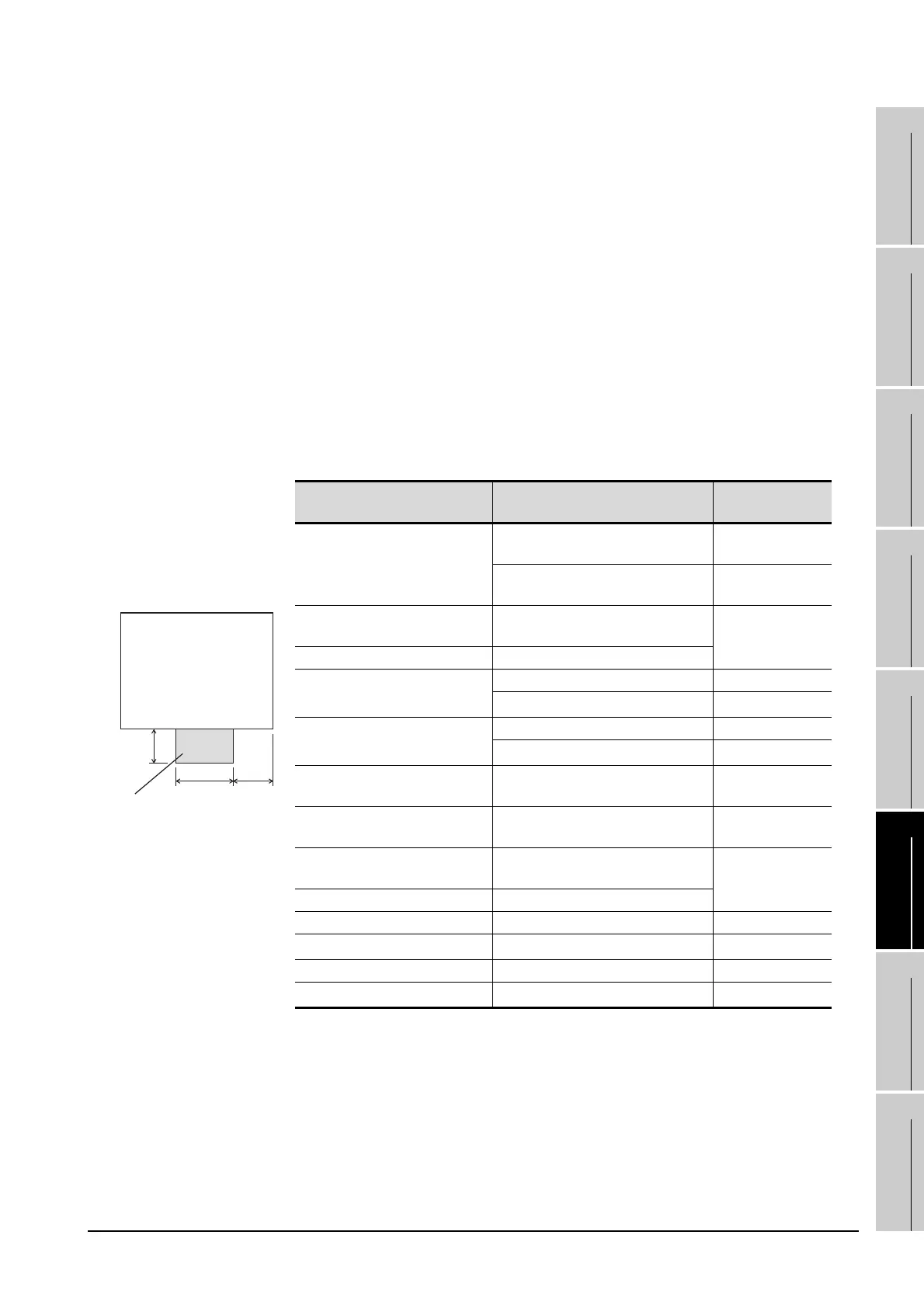
installed in the areas shown in the following figure.
X
Prohibited area for installation
with an extension unit
Hole for installing GOT
(View from the rear side)
130 80
(3.15)(5.12)
Extension unit Model
X
(Unit: mm(inch))
Bus connection unit
GT15-75ABUS2L, CGT15-75ABUSL
GT15-ABUS, CGT15-ABUS2
-
*
GT15-75QBUS2L, CGT15-QBUS2
GT15-75QBUSL, CGT15-QBUS
31(1.38)
Serial communication unit
GT15-RS2-9P, CGT15-RS4-9S
GT15-RS4-TE
-
*
Ethernet communication unit GT15-J71E71-100
MELSECNET/H communication unit
GT15-J71LP23-25 30(1.18)
GT15-J71BR13
-
*
MELSECNET/10 communication
unit
GT15-75J71LP23-Z 68(2.68)
GT15-75J71BR13-Z
-
*
CC-Link IE Controller Network
communication unit
GT15-J71GP23-SX
-
*
CC-Link IE Field Network
communication unit
GT15-J71GF13-T2
-
*
CC-Link communication unit
GT15-J61BT13,
GT15-75J61BT13-Z
-
*
Printer unit GT15-PRN
Video input unit GT15V-75V4 68(2.68)
RGB input unit GT15V-75R1
-
*
Video/RGB input unit GT15V-75V4R1 68(2.68)
RGB output unit GT15V-75ROUT
-
*

 Loading...

