8 - 4
8.1 Communication Unit
8.1.2 Installing procedure
5 When installing an extension unit on the unit that has been installed, refer to the following.
8.1.3 Installing multiple extension units in layers
When not installing an extension unit on the unit that has been installed, in order to avoid receiving
electrostatic, stick accessory stickers to cover the top of mounting screws (2 places).
Keep the connector cover fixed.
Keep the sticker stuck as it is.
(2) GT15-QBUS2, GT15-ABUS2
Sticker
ccessory
stickers
Connector
cover
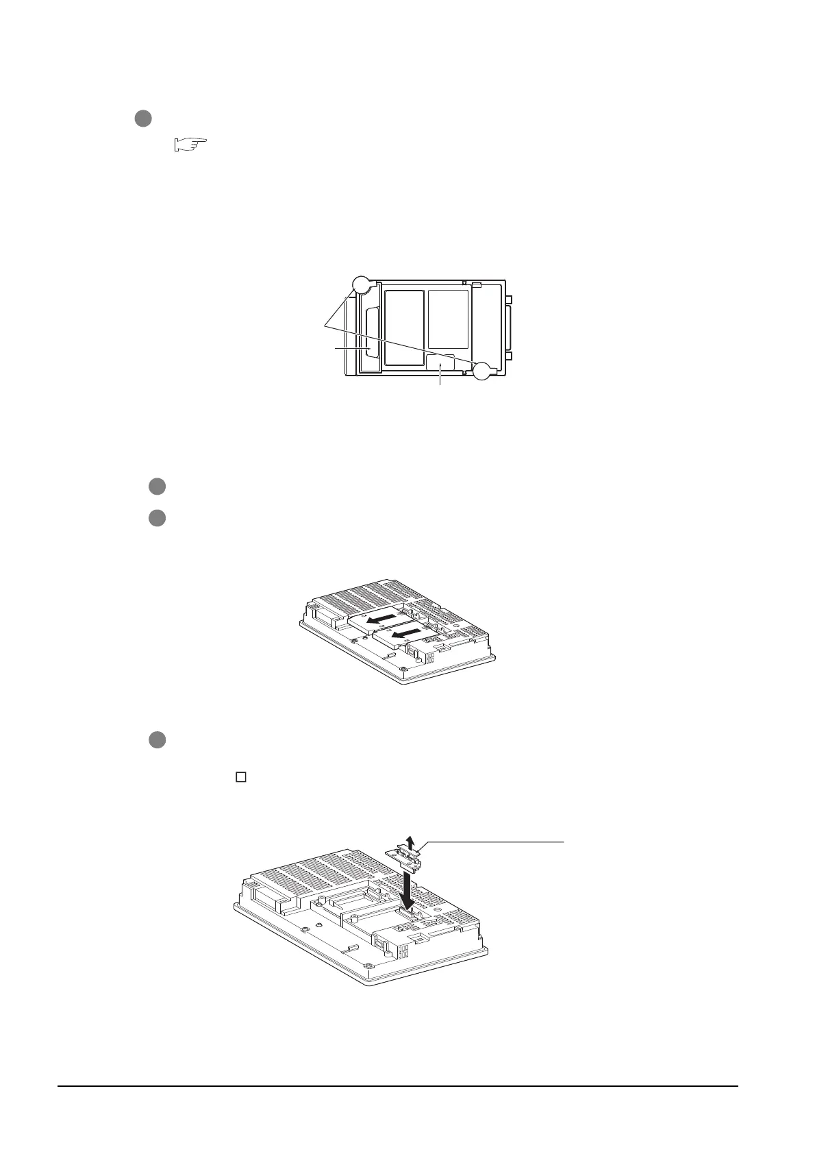
1 Power OFF the GOT.
2 Remove the two extension unit covers of the GOT rear face.
3 Install the extend interface relay board on the Extend I/F-2 side of the GOT.
After the installation, detach the connector cover from the extend interface relay board.
For GT155 , the extension interface relay board is not needed.
Remove the connector cover

 Loading...

