8.1 Communication Unit
8.1.2 Installing procedure
8 - 5
1
OVERVIEW
2
SYSTEM
CONFIGURATION
3
SPECIFICATIONS
4
PART NAME AND
SETTINGS
5
EMC AND LOW
VOLTAGE
DIRECTIVE
6
INSTALLATION
7
WIRING
8
OPTION
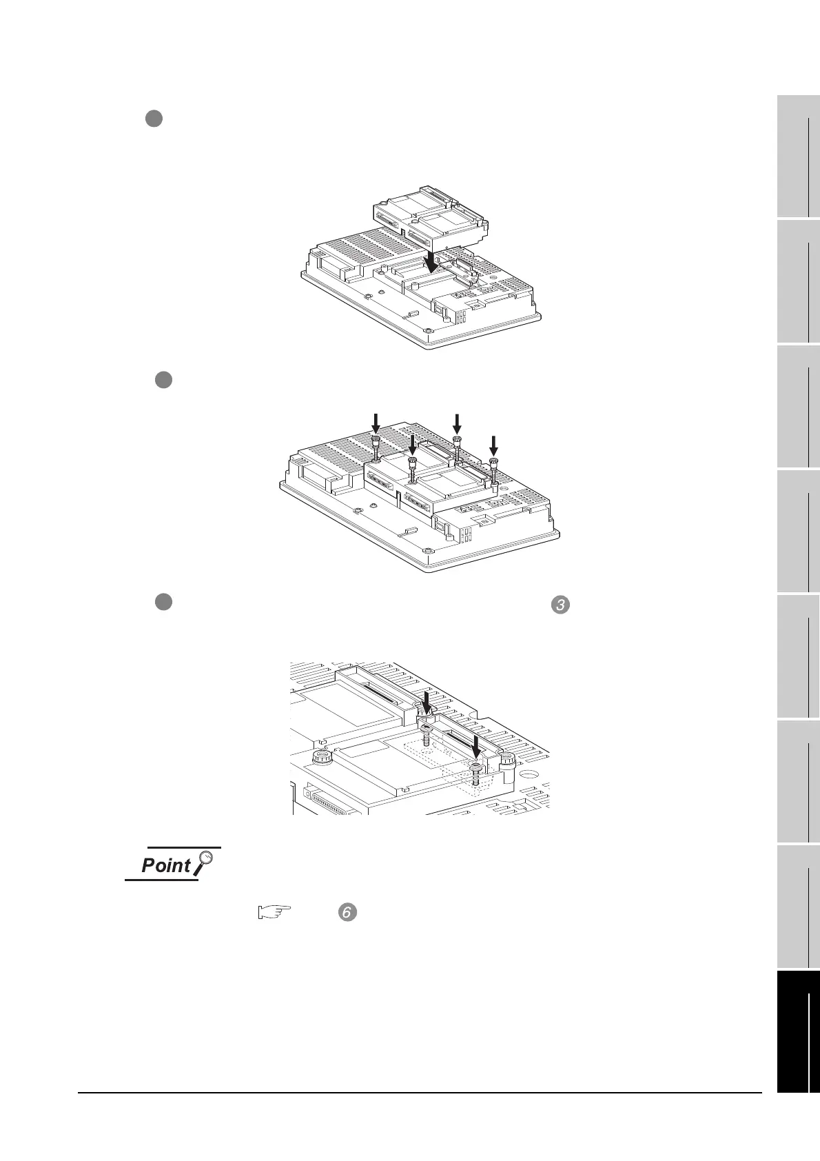
5 After the installation, tighten the mounting screws (4 places) in the specified torque range (0.36
to 0.48N·m).
6 Tighten the extend interface relay board installed by the step within the specified torque
range (0.36 to 0.48N·m). (2 places)
Removing the GT15-QBUS2, GT15-ABUS2
Before removing the unit, unscrew the extend interface relay board fixing screws.
(
above
)
4 Install the communication unit in the extension interface of the GOT rear face.
(When the extension unit is installed in GOT, remove the installed extension unit. And, do not
touch the board in the GOT when install the communication unit.)

 Loading...

